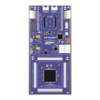
Renesas RA Family MCK-RA6T2 User's Manual
R12UZ0091EJ0100 Rev 1.00 Page 2 of 38
August 3, 2021
6.1.2 Onboard debugger .............................................................................................................................. 28
6.1.3 Inverter board connector ..................................................................................................................... 29
6.1.4 Serial communication .......................................................................................................................... 31
6.1.5 Reset circuit ......................................................................................................................................... 31
6.1.6 LED ...................................................................................................................................................... 32
6.1.7 CAN Communication ........................................................................................................................... 32
6.1.8 SPI communication ............................................................................................................................. 32
6.2 RA6T2 pin function list .......................................................................................................................... 33
7. Communication Board Specification ...................................................................................... 36
7.1 Functions ............................................................................................................................................... 36
7.1.1 Power supply ....................................................................................................................................... 36
7.1.2 USB communication ............................................................................................................................ 36
7.1.3 Serial communication .......................................................................................................................... 36
8. Design and Manufacture Information ..................................................................................... 37
9. Website and Support ............................................................................................................. 37
Figure of contents
Figure 2-1 Product contents .............................................................................................................................. 5
Figure 4-1 MCK-RA6T2 block diagram ........................................................................................................... 10
Figure 4-2 Inveter Board .................................................................................................................................. 11
Figure 4-3 CPU Board ..................................................................................................................................... 11
Figure 4-4 Communication board .................................................................................................................... 12
Figure 4-5 Standoffs and Screws assembly .................................................................................................... 12
Figure 4-6 Default jumper pin setting .............................................................................................................. 13
Figure 4-7 Default jumper pin setting of CPU board ....................................................................................... 15
Figure 4-8 Default jumper pin setting of communication board ....................................................................... 16
Figure 4-9 Board connection ........................................................................................................................... 17
Figure 4-10 Power supply from DC jack .......................................................................................................... 18
Figure 4-11 Power supply from terminal block ................................................................................................ 18
Figure 4-12 Power supply from USB connector .............................................................................................. 19
Figure 5-1 Illustration of inverter control circuit block ...................................................................................... 20
Figure 5-2 Current detection circuit ................................................................................................................. 21
Figure 5-3 Overcurrent detection circuit .......................................................................................................... 22
Figure 5-4 Output voltage detection circuit ...................................................................................................... 23
Figure 6-1 Connection for CPU board and inverter board ............................................................................... 31

 Loading...