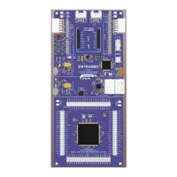
Renesas RA Family MCK-RA6T2 User's Manual
R12UZ0091EJ0100 Rev 1.00 Page 3 of 38
August 3, 2021
Table of contents
Table 4-1 MCK-RA6T2 specification (1/4) ......................................................................................................... 6
Table 4-2 MCK-RA6T2 specification (2/4) ......................................................................................................... 7
Table 4-3 MCK-RA6T2 specification (3/4) ......................................................................................................... 8
Table 4-4 MCK-RA6T2 specification (4/4) ......................................................................................................... 9
Table 4-5 Jumper pin setting of inverter board ................................................................................................ 13
Table 4-6 Jumper pin setting of CPU board .................................................................................................... 14
Table 4-7 Jumper pin setting of communication board ................................................................................... 16
Table 4-8 Power supply and driving voltage generation ................................................................................. 19
Table 5-1 Voltage generation .......................................................................................................................... 23
Table 5-2 LED .................................................................................................................................................. 24
Table 5-3 Toggle switch and push switch........................................................................................................ 24
Table 5-4 Variable resistance specification ..................................................................................................... 24
Table 5-5 CPU board connector (CN3) ........................................................................................................... 25
Table 5-6 CPU board connector (CN4) ........................................................................................................... 26
Table 5-7 Connector for hall sensor signal input (CN6) pin assignment ......................................................... 27
Table 5-8 Pins for encoder/inductive position sensor signal input (CN7) pin assignment .............................. 27
Table 6-1 1st Inverter board connector (CN4) pin assignment ....................................................................... 29
Table 6-2 1st Inverter board connector (CN5) pin assignment ....................................................................... 29
Table 6-3 2nd Inverter board connector (CN7) pin assignment ...................................................................... 30
Table 6-4 2nd Inverter board connector (CN6) pin assignment ...................................................................... 30
Table 6-5 SCI connector (CN10) pin assignment ............................................................................................ 31
Table 6-6 LED pin assignment ........................................................................................................................ 32
Table 6-7 CAN communication pin assignment (CN8) .................................................................................... 32
Table 6-8 SPI communication pin assignment (CN9) ..................................................................................... 32
Table 6-9 RA6T2 pin function list .................................................................................................................... 33
Table 7-1 SCI connector (CN5) pin assignment .............................................................................................. 36
Table 7-2 SCI connector (CN4) pin assignment .............................................................................................. 36

 Loading...