RZ/A2M SUB Board RTK79210XXB00000BE 2. Function specifications
R20UT4398EJ0100 Rev.1.00 2-28
2018.10.11
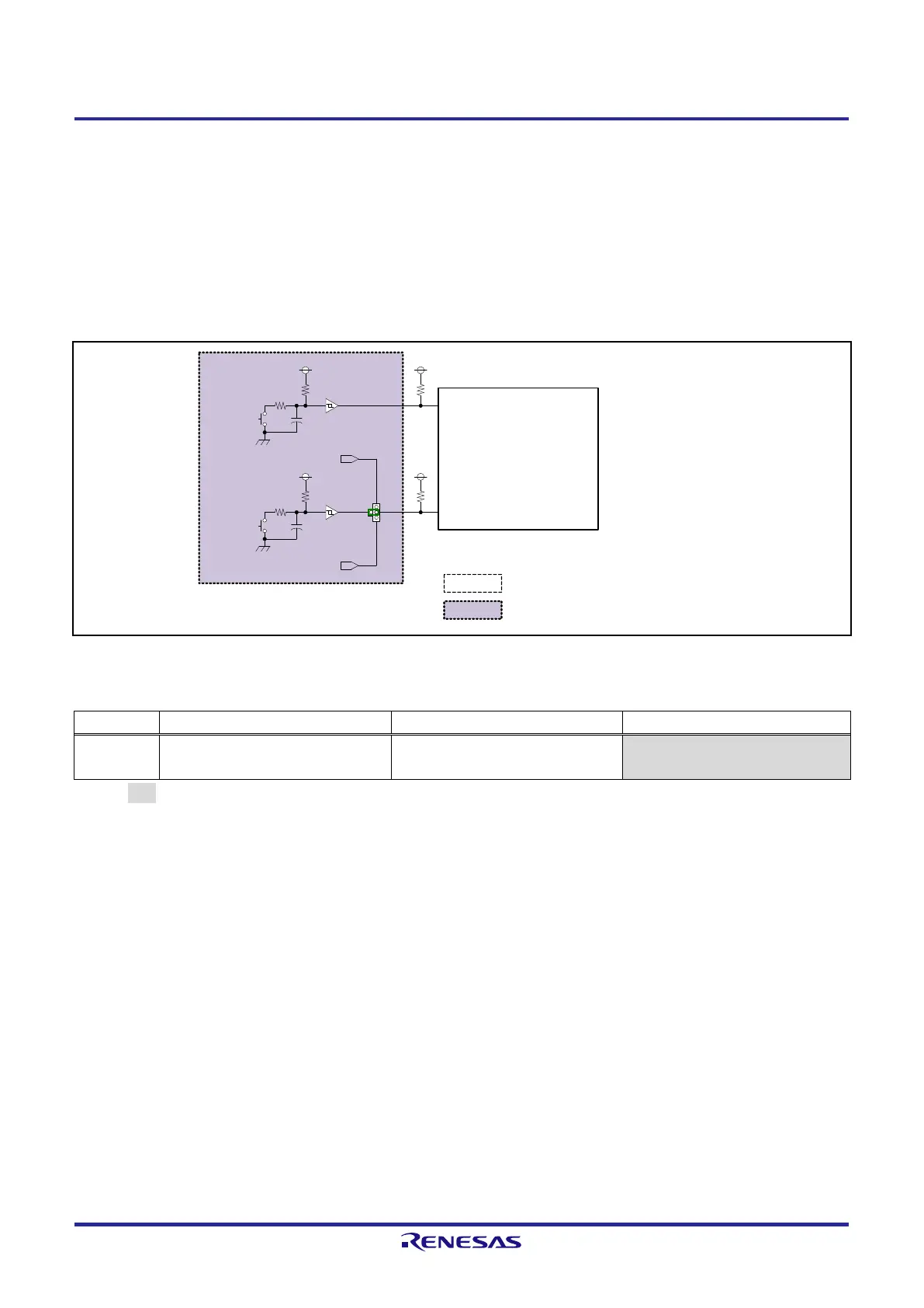
2.6 Interrupt Switches
RTK79210XXB00000BE is equipped with an RZ/A2M NMI and IRQ0 interrupt signal input push switches (NMI
switch and IRQ0 switch).
The interrupt signal from IRQ0 RZ/A2M can be used to cancel the RZ/A2M deep standby mode. However, because
the IRQ0pin is shared with the Ethernet PHY1 and Ethernet PHY2, when using the IRQ0 switch, the user must connect
JP2 with the 2-pin of JP1.
Figure 2.6.1 shows an interrupt switch block diagram, and Table 2.6.1 shows a jumper JP1 function setting table.
Figure 2.6.1 Interrupt Switch Block Diagram
Table 2.6.1 Function Settings for Jumper JP1
3.3V
3.3V
NMI Switch
(SW2)
IRQ0 switch
(SW3)
NMI
RZ/A2M (U1)
PJ_1 / IRQ0 (DSTBY release)
EthernetPHY1.WOL
EthernetPHY2.WOL
1
3
3.3V
3.3V
JP1
JP2
Note: Red text indicates a function used.
:Indicates a function not implemented .
:Indicates a SUB board.
+
+
 Loading...


