EasyManua.ls Logo

Renesas RZ/A Series - Power Voltage Configuration

Renesas RZ/A Series
106 pages
Print Icon
To Next Page IconTo Next Page
To Previous Page IconTo Previous Page
Loading...
RZ/A2M SUB Board RTK79210XXB00000BE 2. Function specifications
R20UT4398EJ0100 Rev.1.00 2-32
2018.10.11
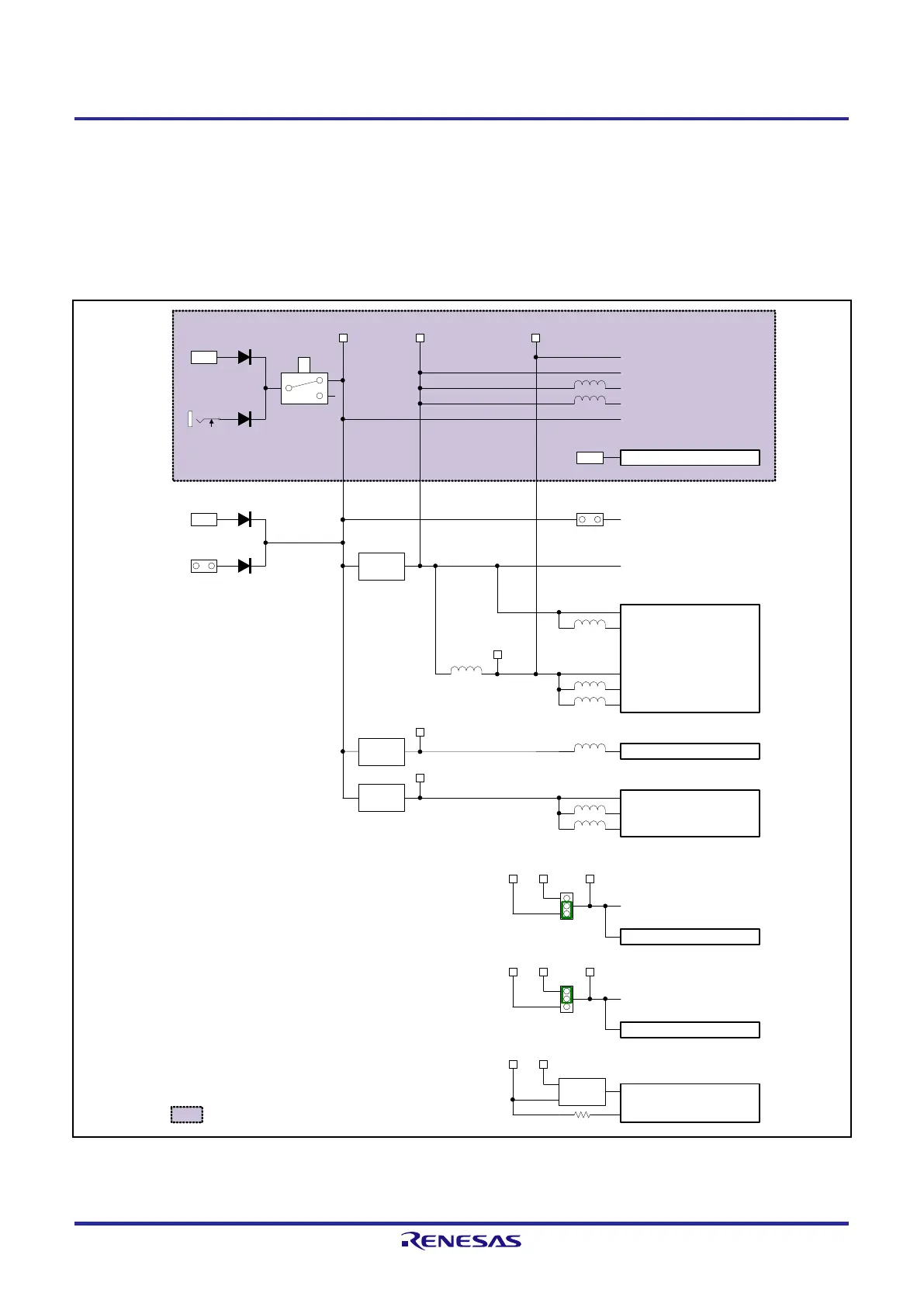
2.9 Power Voltage Configuration
RTK79210XXB00000BE uses 5V power supply, and the regulator on the RZ/A2M CPU board generates 3.3V power
supply. 5V power supply can also be supplied from the RZ/A2M CPU board.
USB serial converter IC (U23) is operated by the VBUS power supply provided from USB Micro-B connector (CN5).
Figure 2.9.1 shows a power configuration diagram.
Figure 2.9.1 Power Configuration Diagram
USB Mini-B
(CN13)
AC adapter
(CN18)
Power source
switch
(SW1)
VBUS
D5V D3.3V AVcc
Ethernet PHY
Audio CODEC
3.3V peripheral device
USB Type-ACN12
Key input switch
Indicates a SUB board.
USB serial converter ICU23
VDD
USB Micro-B
(CN5)
VBUS
5V3.3V
D1.8V
D1.2V
USB Type-C (CN3)
5V external power source
connector (CN4)
5V1.8V
VBUS
PVcc
RZ/A2M (3.3V)
USBDPVcc
AVcc
LVDSAPVcc
USBAPVcc
RZ/A2M (1.8V)
MIPIAVcc18
Vcc
RZ/A2M (1.2V)
LVDSPLLVcc
PLLVcc
3.3V peripheral device
5V1.2V
VBUS power supply
Jumper (JP3)
A3.3V
USB Type-C (CN3)
JP1
D1.8VD3.3V ROMVcc
RZ/A2M (1.8V/3.3V)
PVcc_HO
PVcc_SPI
JP2
D1.8VD3.3V RAMVcc
Serial flash memory (U2)
HyperMCP (U3)
RZ/A2M (1.8V/3.3V)
RZ/A2M (1.8V/3.3V)
PVcc_SD0
D3.3V D1.8V
3.3V/1.8V
Power disconnect
(U4)
PVcc_SD1

Other manuals for Renesas RZ/A Series

Related product manuals