RZ/A2M SUB Board RTK79210XXB00000BE 2. Function specifications
R20UT4398EJ0100 Rev.1.00 2-31
2018.10.11
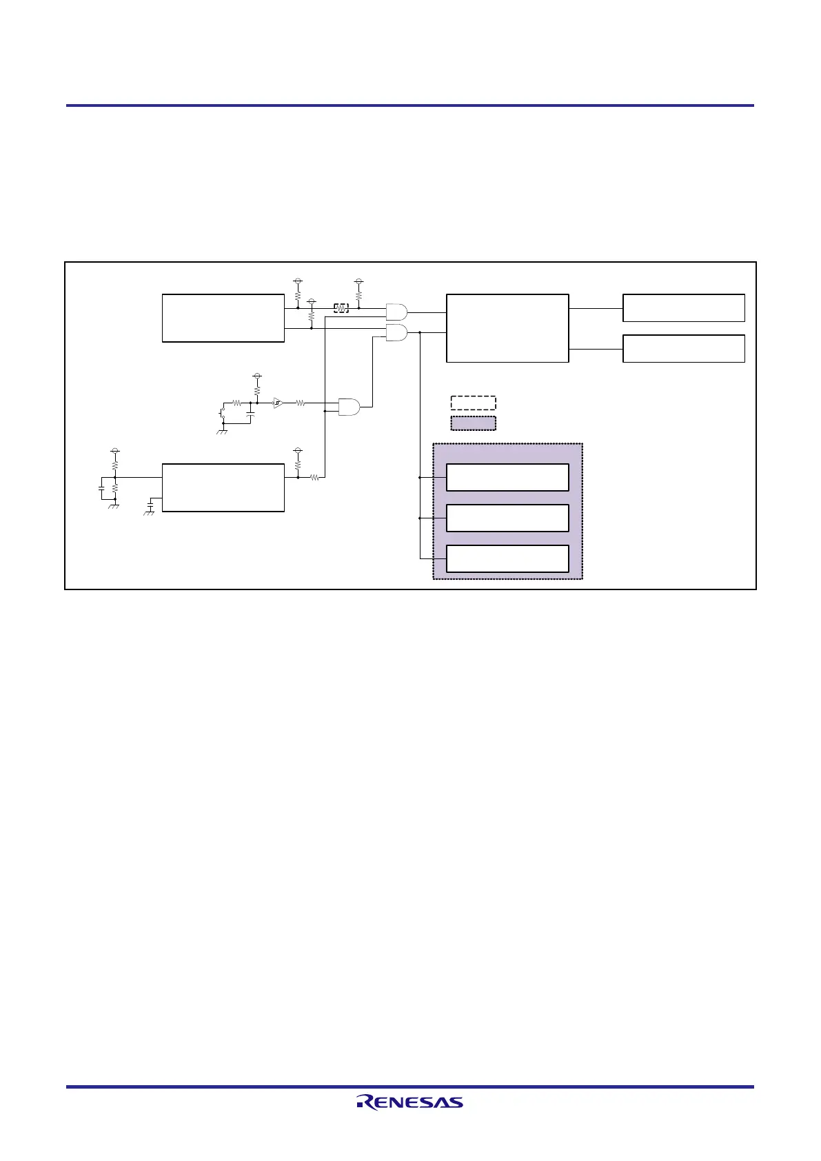
2.8 Reset Control
On RTK79210XXB00000BE, a reset signal from the reset IC on the RZ/A2M CPU board is input to the Ethernet
PHY1 (U27), Ethernet PHY2 (U28), and digital image input/output connector (CN15).
There are two types of system reset: power-on reset and switch-based reset.
Figure 2.8.1 shows a reset control block diagram.
Figure 2.8.1 Reset Control Block Diagram
CoreSight 20 connector (CN5)
TRST#
SRST#
3.3V
3.3V
3.3V
Reset switch (SW2)
Reset IC (U15)
RESET#
CT
SENSE
RZ/A2M (U1)
TRST#
RES#
EthernetPHY1 (U27)
PHYRSTB
EthernetPHY2 (U28)
PHYRSTB
RESET#RPC_RESET#
RESET#HM_RESET#/OM_RESET#
3.3V
VDC6 connector(CN15)
RES#
Note: Red text indicates a function used.
:Indicates a function not implemented.
:Indicates a SUB board.
3.3V
Serial flash memory (U2)
HyperMCP (U3)
+
U12
U13
U14
Reset IC output delay time
tpd=CT(nF)/175+0.5×10
-3
s=27.4ms
reset IC output test voltage
0.405×(Ra+Rb)/Rb=0.405×(130k+20k)/20k=3.04V
3.3V
130k
20k
4700pF
1000pF
 Loading...


