3-9
www.renishaw.com/lp2
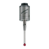
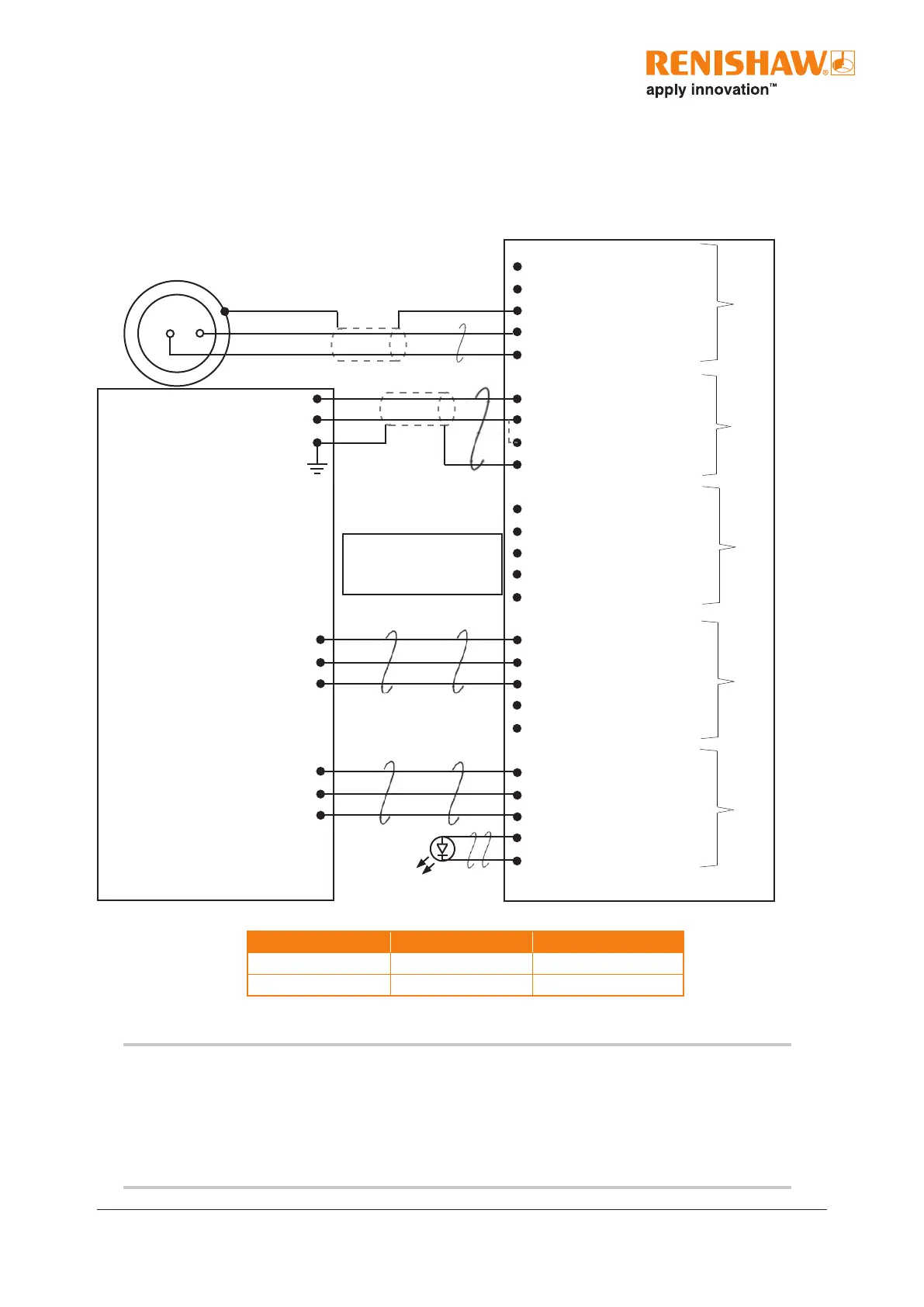
Recommended connection diagram for LP2 with HSI-C
interface
NOTE:
When the SSR output is connected as normally open (NO), the LP2 probe will remain in the
non-triggered (seated) state if the power supply is interrupted or if the probe is damaged.
When connecting the LP2 probe to the HSI-C interface, use the connection labelled STANDARD
PROBE.
HSI-C interface
Probe connector (5-way)
19.
18.
17. Screen
16. Standard probe input +
15. Standard probe input -
Power connector (4-way)
1. +12 Vdc to 30 Vdc supply input
2. 0 Vdc supply
3. 0 Vdc supply
4. Screen
Inhibit connector (5-way)
10. Inhibit input
11. Inhibit return
12. 0 Vdc
13. +12 Vdc to +30 Vdc out (fused at 100 mA)
14. Not connected
SSR probe status connector (5-way)
24. Probe status N/O
23. Probe status common
22. Probe status N/C
21. Not connected
20. Not connected
SSR probe type and external LED
connector (5-way)
29. Probe type N/O
28. Probe type common
27. Probe type N/C
26. External LED 10 Vdc
25. External LED 0 Vdc
Green/Yellow
Outer spring pin, Green
Inner spring pin, Blue
FS1*/FS2*/FS10/FS20 probe holder
xed socket for standard probe
* No screen connection
CNC controller
+12 Vdc to 30 Vdc
0 Vdc
Machine ground (“star point”)
Probe inhibit function, refer to the
HSI-C hard-wired system interface
– congurable installation guide
(Renishaw part no. H-6527-8501) for
connection information
Connect either pin 24
or pin 22, but do not
connect both pins
Connect either pin 29
or pin 27, but do not
connect both pins
Block 4
Block 1
Block 3
Block 5
Block 6
Probe status Normally open (N/O) Normally closed (N/C)
Probe triggered Closed Open
Probe seated Open Closed
 Loading...