3-10
LP2 probe system: System installation
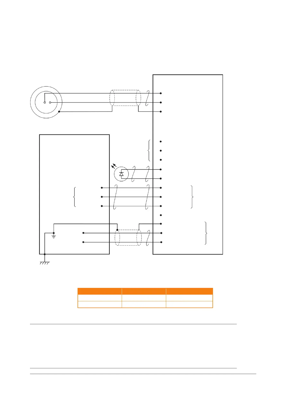
Recommended connection diagram for LP2 with HSI interface
Outer spring pin
Inner spring pin
Probe holder fixed socket
for LP2 probe
HSI
Standard connector (3-way)
1 Probe input +
2 Probe input –
3 Screen
CNC CONTROLLER
Controller connector (12-way)
1 0 V
2 Inhibit return
4 External LED 0 V
5 External LED 10 V
6 NO
7 Common
10 Screen
11 Supply 0 V
12 Supply 12 V to 30 V
8 NC
Status
output
SSR
Power
input
Connect either pin 6 or
pin8, but do not connect
both wires
Probe
input
I/O supply
skip input
Controller protective earth (also
referred to as PE star point or
earth plate)
Screen
0 Vdc
12 Vdc to 30 Vdc
Controller reference ground
9
12 V to 30 V out
(fused 100 mA)
3 Inhibit
Probe inhibit function,
see HSI hard-wired
system interface
installation guide
(Renishaw part no.
H-5500-8554)
Probe status *Normally open (NO) **Normally closed (NC)
Probe triggered Closed Open
Probe seated Open Closed
NOTE:
When the SSR output is connected as normally open (NO), the LP2 probe will remain in the
non-triggered (seated) state if the power supply is interrupted or if the probe is damaged.
When connecting the LP2 probe to the HSI interface, use the connection labelled STANDARD
PROBE.
 Loading...