3-14
LP2 probe system: System installation
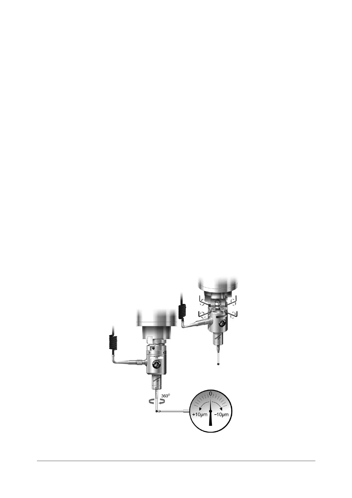
Stylus on-centre adjustment with shank adaptor or shank
1. Shank adaptor only – t shank adaptor onto shank and tighten the shank screws.
2. Attach the MA2 to the shank or shank adaptor. Tighten the two MA2 holding screws, then unscrew
half a turn.
3. Centralise the two MA2 screws at midposition in the MA2 slots.
4. Fit the four on-centre adjusting screws loosely.
5. Insert the probe unit into the machine spindle.
6. Position the dial test indicator (D.T.I.) against the stylus, with light pressure so as not to deect the
stylus.
7. Connect the curly cable to the MA2 and interface. Switch the power on to monitor any accidental
probe trigger during adjustment.
8. Switch the power on to monitor any accidental probe trigger during adjustment.
9. Engage the machine spindle in a neutral or high gear for easy manual rotation. Check the D.T.I. during
spindle rotation. Adjust the four adjusting screws one at a time. Following each adjustment, unscrew
the active screw clear of the centre shaft. Repeat until the stylus is on-centre. Finally, tighten the two
MA2 holding screws and four on-centre adjusting screws.
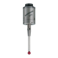
LP2
probe
LP2
probe
MA2 probe
holder
MA2 probe
holder
0.8 Nm – 1.1 Nm
(0.6 lbf.ft – 0.8 lbf.ft)
2.0 mm A/F
× 4
 Loading...