3-11
www.renishaw.com/lp2
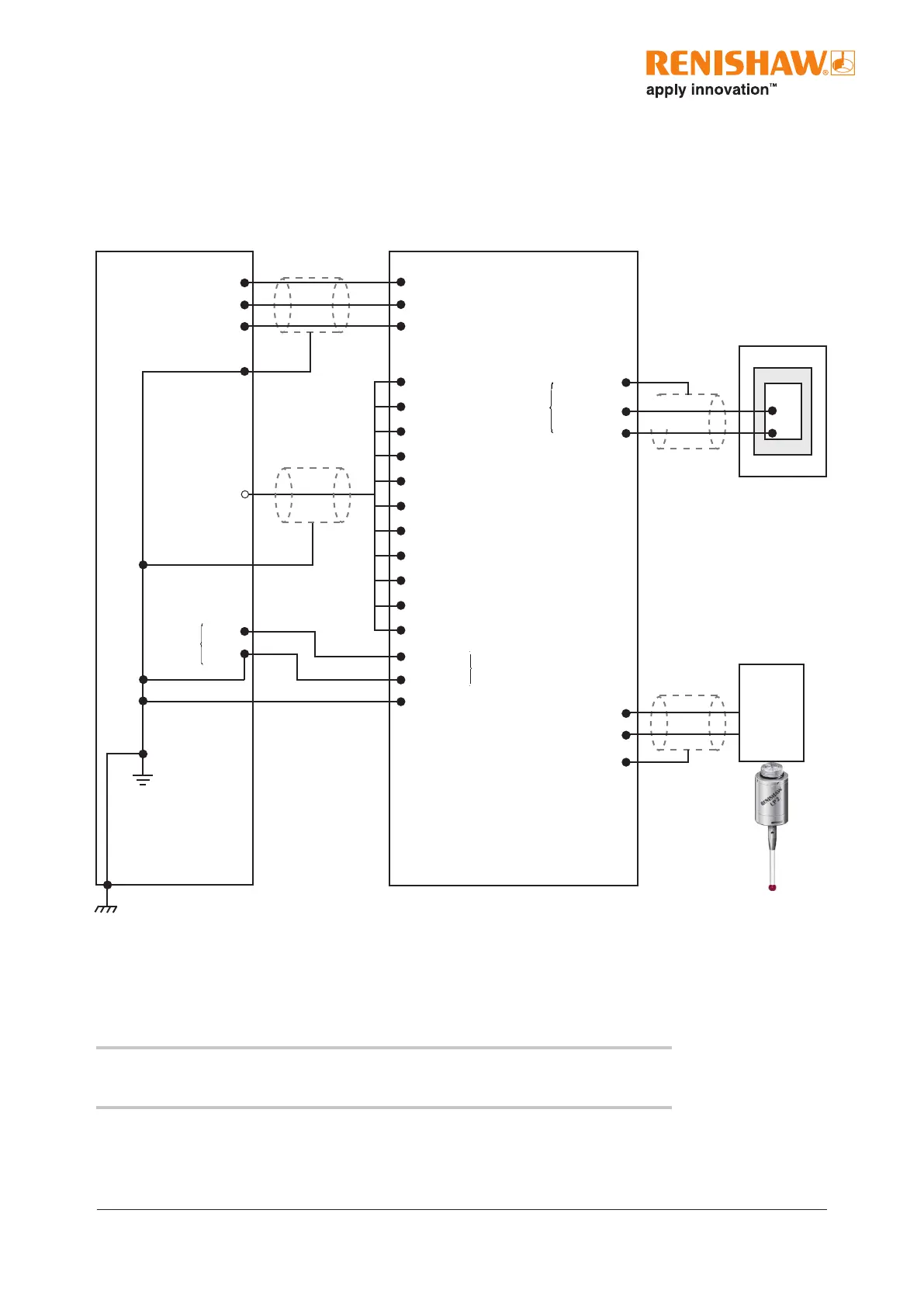
Recommended connection diagram for LP2 with
MI8-4interface
A10 output + supply
A11 probe status output (totem pole)
A12 output - supply
B4 SELX−
B5 X−
B6 SELX+
B7 X−
B8 SELZ−
B9 Z−
B10 SELZ+
B11 Z+
A7 inspection select
A8 inhibit
A9 input resistors common
B1 +Vdc
B2 0 Vdc
B3 screen
Inspection system input + A4
Inspection system input − A5
Screen A6
+Vdc from I/O supply
Skip input (G31)
−Vdc from I/O supply
CNC controller
Green/Yellow
MI 8-4 interface
Optional
Green/Yellow
+ Vdc
0 Vdc
Power to
interface
Green/Yellow
Green/Yellow
Controller
protective
earth
1
Controller
protective
earth
Machine tool
LP2
probe
Optional
Inspection
probe
interface
Inspection
probe
Screen A1
Probe + A2
Probe − A3
Probe
input
Blue
Green
Power
input
1 Can also be referred to as ‘PE starpoint’ or ‘earthplate’
NOTE: For more information regarding these connections, see the MI 8-4 interface
unit installation and user’s guide (Renishaw part no. H-2000-5008).
 Loading...