OMP400 installation guide
3.4
System
installation
MI
1
2
TM
TM
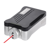
CNC machining centre spindle
CNC
machine
control
Mounting bracket
Cable
Workpiece
OMM
Stylus
Power supply
(optional)
MI 12 interface
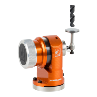
OMP400
inspection probe
Installing the OMP400 with an OMM and MI 12
The probe and OMM diodes must be in the others field of view, and within the performance envelope
shown. The OMP400 performance envelope is based on the OMM being at 0°, and vice-versa.
Natural reflective surfaces within the machine may change the signal transmission range.
Coolant residue accumulating on the OMP400 or OMM windows will have a detrimental effect on
transmission performance. Wipe clean as often as is necessary to maintain unrestricted transmission.
Operation in temperatures of 0 °C to 5 °C or 50 °C to 60 °C (32 °F to 41 °F or 122 °F to 140 °F) will
result in some reduction in range.
On large machine tools, it is possible to provide greater reception coverage by mounting two OMMs
connected to a single MI 12 interface.
CAUTION: If two systems are operating in close proximity to each other, take care to ensure that
signals transmitted from the OMP400 on one machine are not received by the receiver on the other
machine, and vice versa. When this is the case, use of the probe’s low power mode or OMM low range
setting