— 10 —
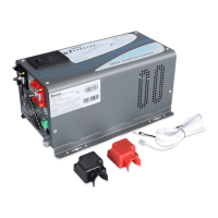
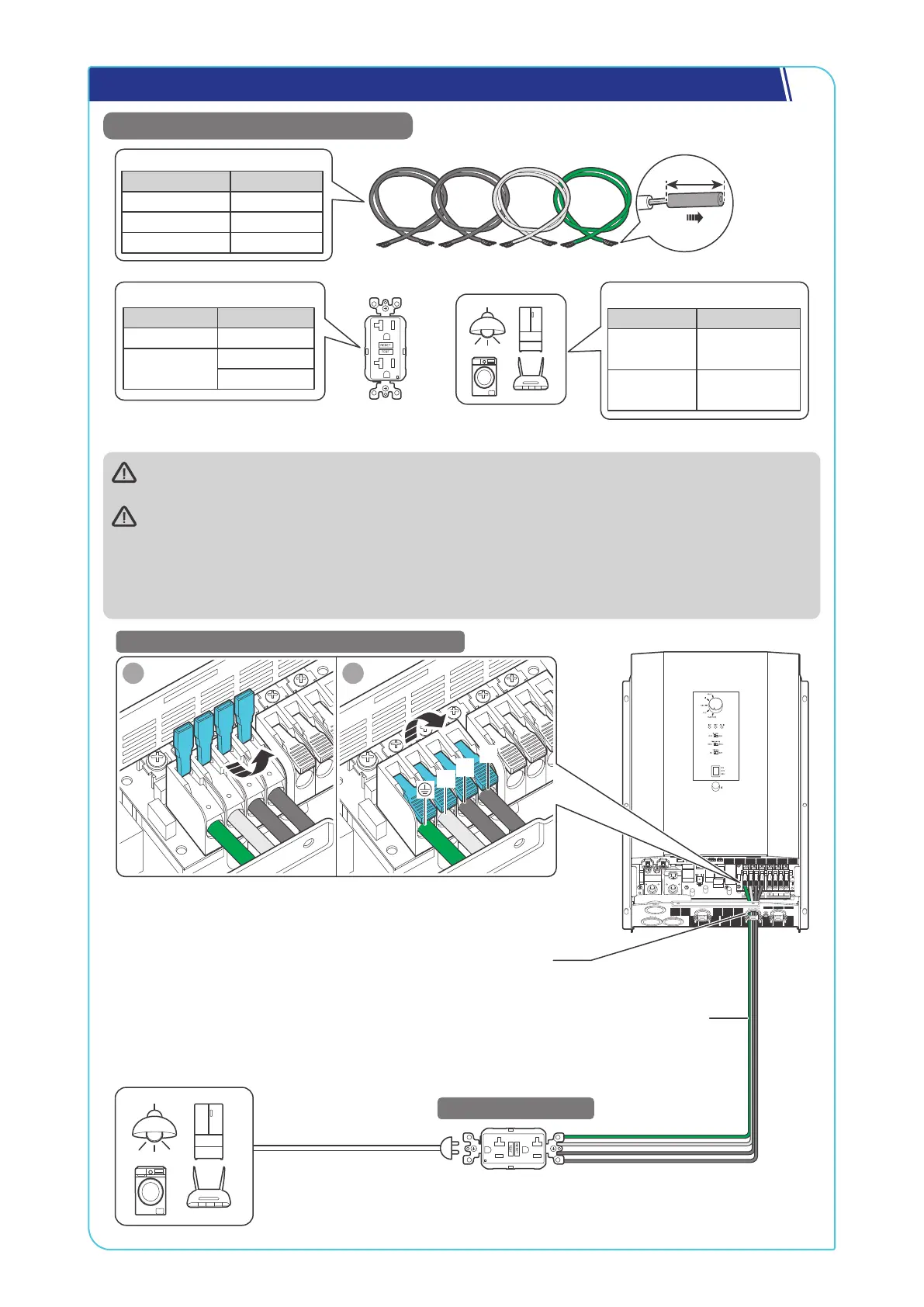
Step 9. Connect the Inverter Charger to AC Loads (Appliances)
Recommended Components & Accessories
Ground Fault Circuit
AC Loads
Recommended GFCI Spec
Grid Power Ratings
Unavailable
≥25A@120V
Available
≥50A@120V
≥25A@240V
Total Load Power
Grid Power Ratings
Unavailable
≤3000W
@120V
≤6000W
@120V/240V
Available
Bare Wires × 4
Recommended Cable Size
Cable Length Cable Size
0 ft to 10 ft 6 AWG
11 ft to 20 ft 4 to 6 AWG
21 ft to 30 ft 4 AWG
For details on how to connect loads and the inverter charger to the GFCI, read the user manual of the
specific GFCI.
For split-phase 120V/240V grid systems where AC IN L1, L2, and N are used:
z
When the AC output is connected to L1, L2, and N, the inverter charger outputs 240V.
z
When the AC output is connected to L1 and N, the inverter charger outputs 120V.
For single-phase 120V grid systems or when there is no available grid power, the inverter charger
outputs 120V.
N L2
AC OUT
L1 N L2
AC IN
L1
BAT-
BAT+
1 2
STEP-1 Install Bare Wires on the Inverter Charger
STEP-2 Install a GFCI
L1
N
L2
Bare Wires
Through the grommet of the AC Output Port
 Loading...