— 12 —
Step 11. CAN Communication Wiring (Optional)
You can connect the inverter charger to other REGO devices for real-time inter-device data communication
through any of the CAN1 Port.
The wiring details vary depending on the wiring schemes. This quick guide elaborates on inter-device wiring in
two schemes: backbone and daisy chain.
For technical support from Renogy, please contact us through renogy.com/contact-us/.
For wiring details, refer to the REGO 12V 3000W HF Inverter Charger User Manual at https://www.
renogy.com/support/downloads.
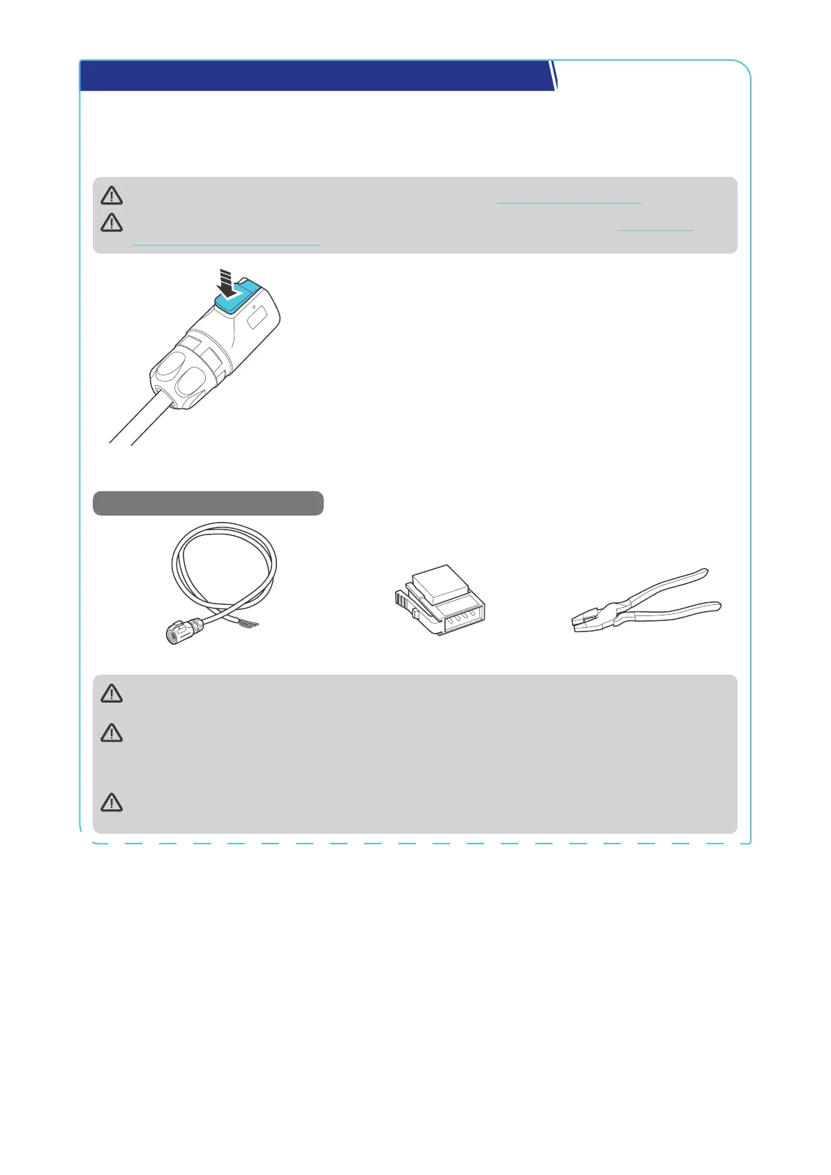
To properly connect or disconnect the LP16 Terminal Plug to or from the
inverter charger, you should
1. Ensure that the plug is oriented vertically toward the CAN1
Communication Port.
2. Press and hold the snap until the process is complete.
Shaking while plugging or unplugging is not allowed.
Backbone Network
Recommended Tools & Accessories
LP16 Plug (7-Pin) to Bare Drop Cable(s) Drop Plugs Split Joint Pliers
Ensure 120
Ω
terminating resistors are installed at both ends of the RV-C bus for successful
communication with REGO series devices.
Choose the appropriate drop plugs that are compatible with the drop sockets used on the RV-C bus.
Different RV manufacturers may use different types of drop sockets for inter-device communication
connections. If you are unsure about the correct drop plug selection, consult with the RV
manufacturer. In this quick guide, the Mini-Clamp II plug (4-pin) is used as an example.
Different Drop Plugs follow different pinouts. Crimp the Drop Plugs on the Drop Cables following the
correct pinout. If you are not sure about the Drop Plug pinout, check with the RV manufacturer.
 Loading...