— 11 —
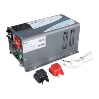
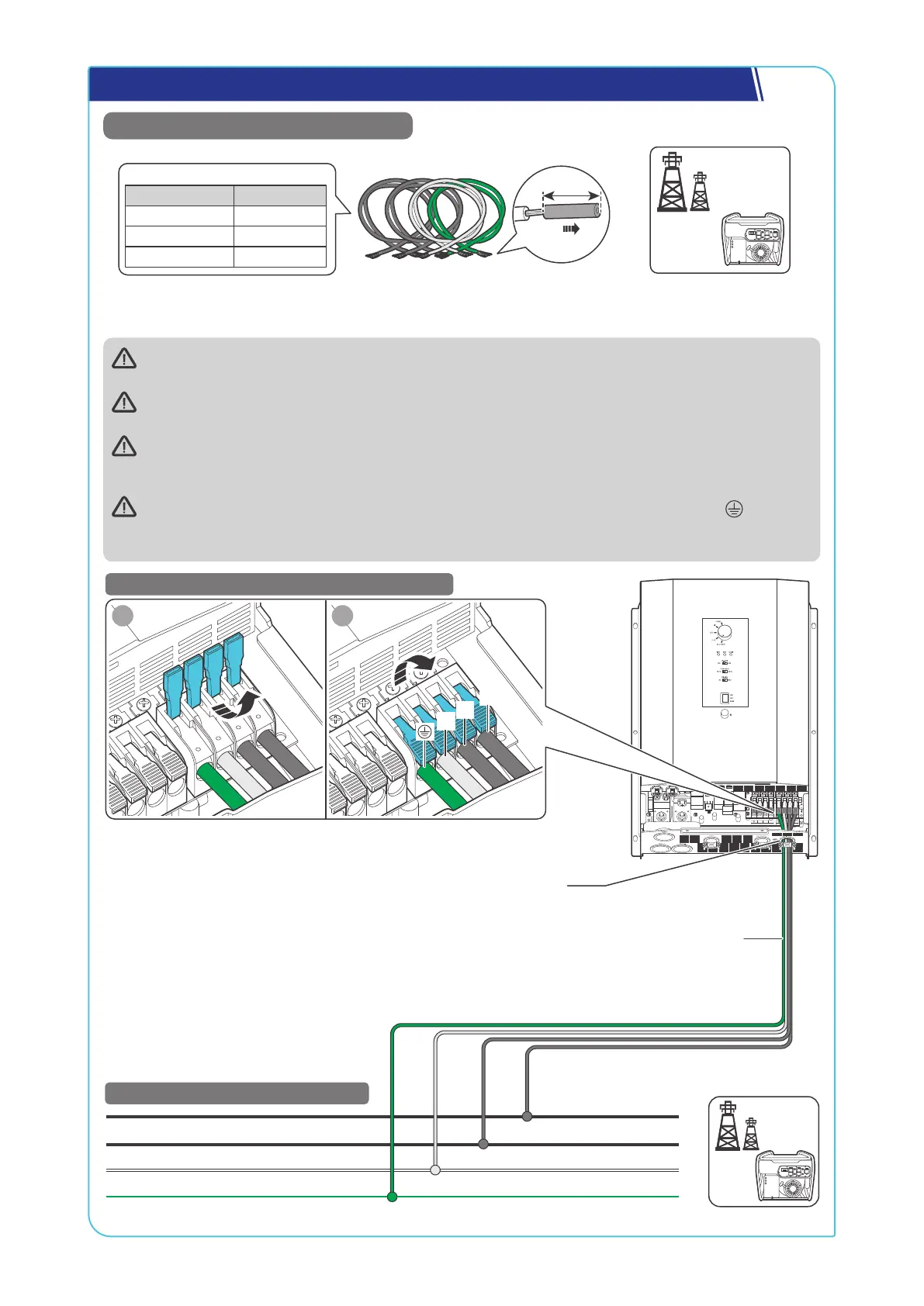
Step 10. Connect the Inverter Charger to the Grid (Optional)
Recommended Components & Accessories
Bare Wires × 4
Grid Power
(Single-phase 120V or
Recommended Cable Size
Cable Length Cable Size
0 ft to 10 ft 6 AWG
11 ft to 20 ft 4 to 6 AWG
21 ft to 30 ft 4 AWG
AC
Generator
Risk of electric shock! Ensure the grid or the AC generator is turned off before connecting them to the
inverter charger.
For details on how to connect the AC Generator to the inverter charger, read the user manual of the
specific generator.
The connection of AC IN ports vary depending on the connected grid systems. For single-phase 120V
grid systems, only AC IN L1 and N ports are used for the input. For split-phase 120V/240V grid systems,
AC IN L1, L2, and N ports are used for the input.
If there is no available grid contact, connect the ground bare wire (one end connecting to ) to the N
bare wire as shown in the figure below. Failure to follow this step may result in charging/discharging
issues with grid power, along with fault alarms.
L1
N
PE
STEP-2 连接信号线.
STEP-2 Install Bare Wires on the Grid
L2
N L2
AC OUT
L1 N L2
AC IN
L1
BAT-
BAT+
Through the grommet of the AC Input Port
STEP-1 Install Bare Wires on the Inverter Charger
1 2
L1
N
L2
Bare Wires
 Loading...