— 3 —
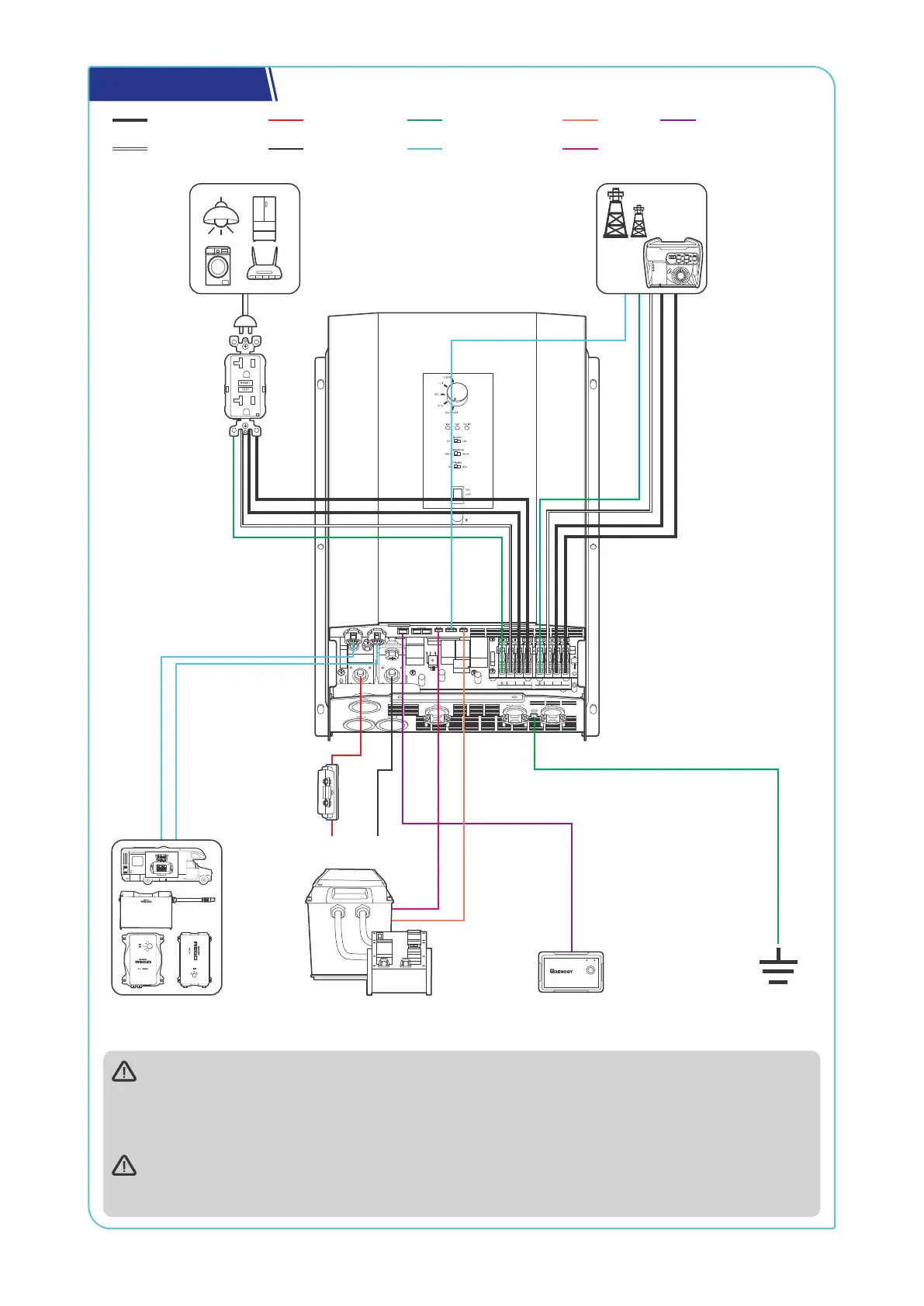
System Setup
N L2
AC OUT
L1 N L2
AC IN
L1
BA T-
BAT+
Communication
BVSNegative (DC)
Neutral wire (AC)
Battery System
(12V)
Fuse
(400A)
RV-C or REGO
Series Devices
+
-
AC Loads
Ground
Fault
Circuit
Interrupter
(GFCI)
Wired Remote
Control
ON ERR
RMS-P2
DC-DC Battery Charger
Grid Power
The wiring diagram only shows the key components in a typical DC-coupled off-grid energy
storage system for the illustrative purpose. The wiring might be different depending on the system
configuration. Additional safety devices, including disconnect switches, emergency stops, and rapid
shutdown devices, might be required. Wire the system in accordance with the regulations at the
installation site.
The connection of AC IN ports vary depending on the connected grid systems. For single-phase 120V
grid systems, only AC IN L1 and N ports are used for the input. For split-phase 120V/240V grid systems,
AC IN L1, L2, and N ports are used for the input.
 Loading...