10
INSTALLING THE CONTROL PANEL
1. Undo the two cover xing screws on top of the panel
and open the cover. The cover is hinged along the
bottom edge.
2. Unclip and remove the two back-up batteries on
either side of the panel.
3. Hold the Control Panel in position on the wall and
mark the positions of the four xing holes. Remove the
panel, drill four 5mm holes and t the 22mm wall plugs.
Note: The wall plugs supplied with the product are not
suitable for plasterboard walls. If mounting the Control
Panel onto plasterboard use appropriate wall plugs.
4. Fit two 18mm No.4 screws into the top holes until
3mm protrudes from the wall face and hang the Control
Panel over these screws using the two keyhole slots in
the top corners of the panel casing.
5. Route the cable from the Power Supply Adaptor up
behind and on the right hand side of the Control Panel
and connect the plug to the DC power socket in the
IMPORTANT: Do not drill the xing holes with the
Control Panel in position; as the resulting dust and
vibration may damage the Control Panel’s internal
components and invalidate the guarantee.
panel. Ensuring that the cable is not trapped between
the panel and the wall.
6. Fix the Control Panel to the wall using two 18mm
No.4 screws in the lower two xing holes in the Control
Panel and tighten the upper xing screws until they just
grip the casing. Do not over tighten the screws as this
could damage or distort the casing.
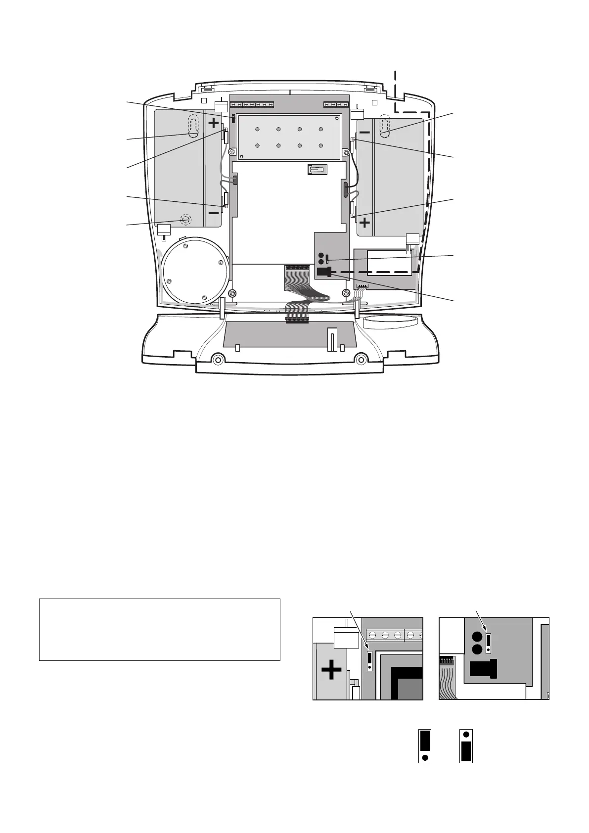
7. Ensure that the Reset Jumper Link (P1) and the
External Tamper Switch Jumper Link (P51) are set in
the OFF position.
TAMP GND B+ GND N.C. C N.O. GND V+ OUT GND
External Tamper Switch
Jumper Link P51
Reset Jumper
Link P1
Jumper
Link
Jumper
Link
Inside View of Control Panel