8
Typical Installation using only the
detectors supplied:
1. Place the 1
st
Magnetic Contact Detector (congured
on zone 1) on the front door.
2. Place the 1
st
PIR Detector (also congured on zone
1) in the hall covering the Control Panel and routes
between downstairs rooms.
3. Place the 2
nd
Magnetic Contact Detector (congured
on zone 2) on the back or Patio doors.
4. Place the 2
nd
PIR Detector either
i) downstairs in the main living room containing
most valuables, (set on zone 3), or
ii) upstairs on the landing covering the access
routes between bedrooms and the stairs, (set on
zone 5). This will be inactive if Part-Arm is used.
The system may be expanded with additional detectors,
Remote Controls and Keypads to provide even greater
protection. However, the following rules should be
followed:
a. Any detectors covering the main door and the
route to the Control Panel should be set on zone 1
only.
b. Any detectors covering the remainder of the
lower oor should be set on zones 2 to 4 only.
c. Any detectors placed upstairs should be set on
zones 5 or 6 only.
The pre-congured system defaults provide a basic
functional system which will suit most installations, (i.e.
a 2 oor house):
The systems factory settings are pre-congured to
provide a basic functional system to suit most typical
basic installations:
• The system has a 3 minute alarm duration.
• The Zone Lockout feature is ON so that if any single
zone triggers an alarm more than 3 times, alarm signals
from that zone will be ignored until the system is next
re-armed.
• Detectors on Zone 1 (typically the front door and
hallway) will have a 30 second entry/exit delay period.
Detectors on all other zones are congured as
INSTANT, (i.e. they have no entry/exit delay).
Note: All system devices must be congured with
the same House Code.
• Part-Arm is congured to operate with detectors on
zones 1 to 4 only.
Note: If you wish to change the system conguration
away from the above example and factory settings to
customise it to your own unique requirements then refer
to the Programming section on page 22
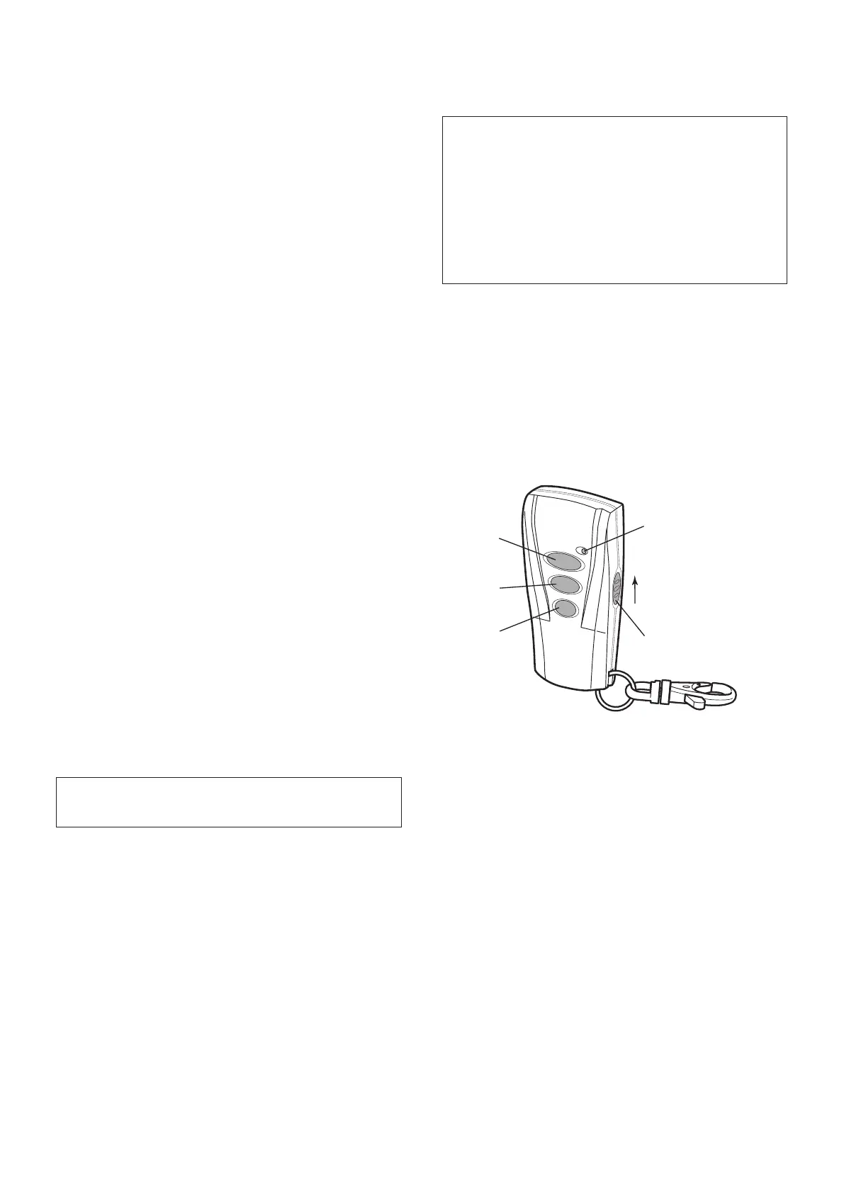
REMOTE CONTROL UNIT
The Remote Control Unit(s) are used to Arm, Part-Arm
and Disarm the system.
The Remote Control Unit also incorporates a Personal
Attack (PA) switch. Activating the PA switch on the
side of the Remote Control will immediately trigger an
Alarm (unless the Control Panel is in Test or Program
Modes) even if the system is disarmed. The alarm can
be cancelled by pressing the ’DISARM’ button on the
Remote Control or at the Control Panel.
Any number of Remote Control Units can be used with
your system, providing they are all coded with the same
system House Code (DIP switch settings).
The Remote Control is powered by a CR2032 type
Lithium cell which under normal conditions will have an
expected life of approximately 1 year. Under normal
battery conditions the Transmit LED on the Remote
Control will only illuminate when a button is pressed.
IMPORTANT: All system devices must be set to the
same House Code.
The default User Access Code for the Control Panel
is “1234”. As soon as installation is complete, this
should be changed to your own code that only
you and other system users know (see page 22 to
change the code).