19
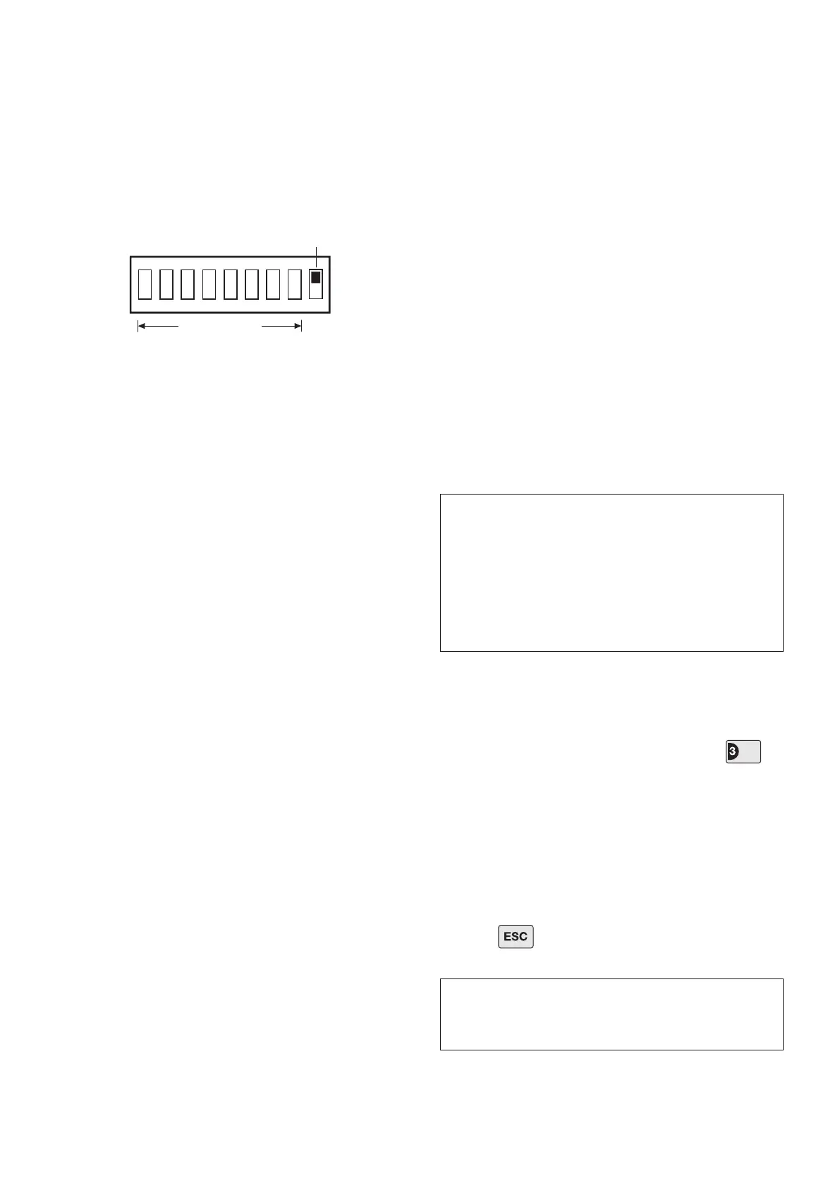
8. Under the cover you will nd a series of 9 DIP
switches.
Note: When the Siren is viewed as shown above (Solar
Panel at top) the DIP switches are ‘upside down’.
9. DIP switches 1-8 are used to set the House Code
for the Siren and must be set to the same ON/OFF
combination as all other system devices.
10. If required, the maximum length of time that the
Siren will sound for when activated under an alarm
condition may be limited to 3 minutes using DIP switch
9 as follows:
ON as Control Panel setting
OFF limited to 3 minutes
11. The Siren will acknowledge Disarm signals from the
Remote Control and Service Mode signals by beeping.
It is possible to disable these acknowledgement beeps
if required by removing the jumper link P2 on the circuit
board.
P2 tted Beep enabled
P2 removed Beep disabled
12. If for any reason you need to disable the Siren,
remove jumper link P3 on the circuit board. This
will prevent the Siren from sounding during an
alarm condition. However, the Siren will still beep
to acknowledge signals from the Remote Control,
(provided the beep feature has not been disabled).
P3 tted Siren enabled
P3 removed Siren disabled
Important: The jumper link (P3) is small so will need to
be stored in a safe place until you need to reinstate the
Siren alarm.
13. To enable the Jamming Detect feature in the Siren
t the jumper link taped to the cover of the Siren control
unit across link pins P1 on the circuit board.
P1 tted Jamming Detection enabled
P1 removed Jamming Detection disabled
14. Ret the DIP switch cover and replace the 3 cover
xing screws. Do not over tighten the screw as this
could damage the thread.
POWERING UP THE SIREN
1. Connect the 9V PP3 power-up battery to the battery
clip.
Connect the rechargeable battery to the charging
leads. Connect the Red lead to the Red ( + ) terminal
and the Black lead to the Black ( - ) terminals. Both
indicator LEDs will ash together in a single long ash
to indicate that the unit is operational.
2. Press the tamper switch, both indicator LEDs
will ash together several times. The LEDs will
then continue to ash alternately every 10 seconds
thereafter to indicate that the Siren is functioning.
3. Hinge the front cover locating tabs over the top
edge of the back plate and carefully push the base of
the siren cover into place. Secure the Siren cover in
place by retting the xing screw in the bottom edge of
the cover. Do not over tighten the screw as this could
damage the thread.
4. If tted remove the protective lm covering the Solar
Panel.
Testing the Siren:
5. With the Control Panel in Test Mode, press to
select Siren Test.
The Control Panel alarm and the External Siren will be
operated for a period of approximately 5 seconds. The
External Siren will switch ON and OFF a few seconds
after the Control Panel.
Zone LED 3 will be illuminated during the test.
6. Press to return the Control Panel to the top
level of Test Mode.
IMPORTANT: Ensure that the rear tamper switch
is closed when you t the siren cover to the back-
plate (i.e. listen for the switch to click). If the
switch does not close it will prevent the Siren from
operating correctly. If necessary, remove the siren
cover again and adjust the screw on the back-plate
tamper plunger to ensure the switch closes when
the Siren is secured in position.
IMPORTANT: The Siren must now be left in position
for at least 24 hours to fully charge the Main Battery
before testing or operating the alarm.