13
The Position of the Circuit Board inside the PIR can
be set to 5 different positions to adjust the range of
the detection pattern created by the PIR. Setting the
Circuit Board in position 3 will reduce the range to
approximately 9 metres, with position 1 providing a
range of approximately 6 metres. The recommended
position setting for the Circuit Board is in position 5.
When deciding upon the mounting position for the
detector the following points should be considered to
ensure trouble free operation:
1. Do not position the Detector facing a window or
where it is exposed to or facing direct sunlight. PIR
Detectors are not suitable for use in conservatories.
2. Do not position the Detector where it is exposed to
draughts.
3. Do not position the Detector directly above a heat
source, (e.g. re, radiator, boiler, etc).
4. Where possible, mount the Detector in the corner of
the room so that the logical path of an intruder would
cut across the fan detection pattern. PIR Detectors
respond more effectively to movement across the
device than to movement directly towards it.
5. Do not position the Detector in a position where it is
subject to excessive vibration.
6. Ensure that the position selected for the PIR
Detector is within effective range of the Control Panel.
Do not x the PIR Detector onto or very close to
metalwork (i.e. radiators, water pipes, etc) as this could
affect the radio range of the device.
Note: When the system is Armed, pets should not be
allowed into an area protected by a PIR Detector as
their movement could be detected and trigger an alarm.
INSTALLING AND CONFIGURING THE
PIR DETECTORS
Ensure that the system is in Test Mode (see page 20).
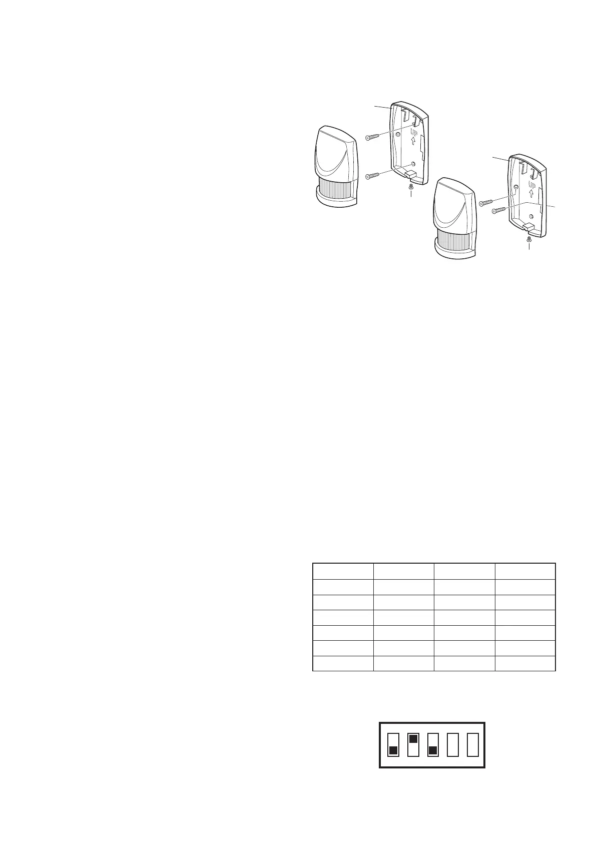
1. Undo and remove the xing screw from the bottom
edge of the PIR Detector, (keep the screw safe for
later). Carefully pull the bottom edge of the detector
away from the rear cover and then slide down to
release the top clips.
2. Carefully drill out the required mounting holes in the
rear cover using a 3mm drill according to whether the
unit is being mounted in a corner or against a at wall.
3. Using the rear cover as a template, mark the
positions of the xing holes on the wall.
4. Fix the rear cover to the wall using the two 18mm
No.4 screws and 22mm wall plugs, (a 5mm hole will be
required for the wall plugs). Do not over- tighten the
screws as this may distort or damage the cover.
Note: The wall plugs supplied with the product are not
suitable for plasterboard walls, if mounting the Detector
onto plasterboard use appropriate wall plugs.
5. Congure the House Code for the PIR Detector by
setting DIP switches 1-8 of SW2 to the same ON/OFF
combination as the House Code DIP switches in all
other system devices.
6. Congure the alarm zone which the detector will
operate on by setting DIP switches 1-3 of SW3 as
follows:
e.g. To congure the detector to operate on zone 3 set
DIP switches 1, 2 and 3 of SW3 as follows:
DIP 1 DIP 2 DIP 3
Zone 1 OFF OFF OFF
Zone 2 OFF OFF ON
Zone 3 OFF ON OFF
Zone 4 OFF ON ON
Zone 5 ON OFF OFF
Zone 6 ON OFF ON