14
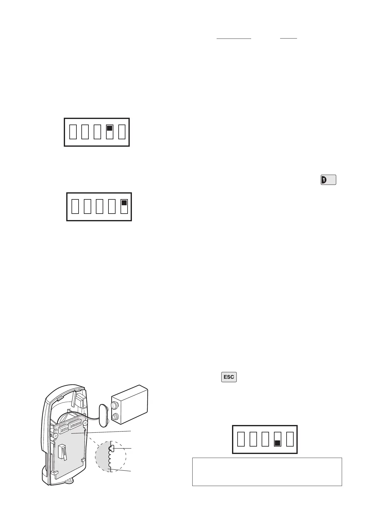
7. DIP switch 4 of SW3 is used to congure the PIR
Detector for Walk Test, which overrides the 2 minute
sleep period and allows the operation of the detector to
be checked during installation.
ON Walk Test
OFF Normal Operation
On initial installation the detector should be congured
into Walk Test ready for testing, (i.e. with DIP switch 4
of SW3 ON).
8. To select the required sensitivity, set DIP switch 5 of
SW3 as follows:
ON HIGH sensitivity
OFF LOW sensitivity
Note: The recommended setting is HIGH. However,
in cases of extreme environmental problems or if
unexplained false alarms are experienced, it may be
necessary to set the sensitivity to LOW. Setting the
device to LOW sensitivity will require a greater amount
of movement in order to trigger the device.
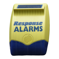
9. Connect the PP3 Alkaline battery to the battery
clip. The LED behind the lens will rapidly ash for
approximately 2-3 minutes until the PIR has stabilised.
The LED will then stop ashing and turn OFF.
10. Check that the detector Circuit Board is located and
set in the correct position to give the detection zone
pattern required.
To adjust the PCB position simply slide it up or down
ensuring that the location legs are aligned with the
required position number marked on the Circuit Board.
11. Ret the PIR Detector to the rear cover by offering
the detector up to the rear cover and locate the clips in
the top edge into the rear cover. Push the lower edge
of the detector into place and ret the xing screw in
the bottom edge of the PIR to secure in position. Do
not over-tighten the screws as this may damage the
casing.
Testing the PIR Detector:
12. Ensure that the LED indicator has stopped ashing
rapidly.
13. With the Control Panel in Test Mode, press
to select Detector Test.
The panel will beep and the zone 1 LED will illuminate.
14. Walk into and move slowly around the protected
area, each time the detector senses movement the
LED indicator behind the lens will ash.
In addition, the Control Panel will beep to indicate that
the alarm signal has been received and the appropriate
zone LED that the detector is congured on will ash.
15. If necessary remove the detector from the wall and
adjust the mounting position of the circuit board within
the detector. Repeat step 14 until the detection range
is correct for your needs. (In most cases no adjustment
will be required).
16. Remove the back cover of the PIR Detector. The
Control Panel should beep and the TAMPER LED will
ash to show that the detector’s tamper switch has
been activated.
17. Press to return the Control Panel to the top
level of Test Mode.
18. Recongure the PIR Detector for normal operation
with DIP switch 4 of SW3 OFF and ret in position on
the wall.
1 6m
3 9m
5 12m
PCB Position Range
IMPORTANT: In normal operation, the LED indicator
behind the detector lens will not ash on movement
detection, (unless the battery is low).