17
Testing the Magnetic Contact Detector:
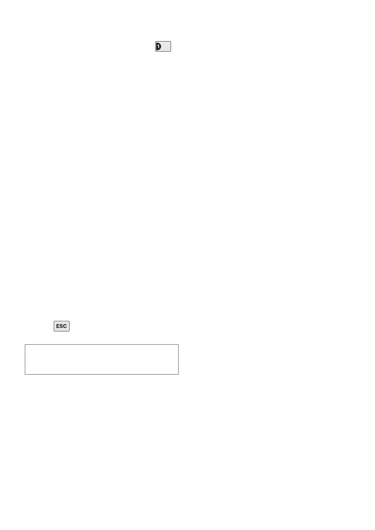
10. With the Control Panel in Test Mode, press to
select Detector Test.
The panel will beep and the zone 1 LED will illuminate.
11. Remove the battery cover to activate the tamper
switch.
As the button is released the LED indicator will
illuminate for approximately 1 second to show that the
tamper switch has been triggered and a signal is being
transmitted.
In addition, the Control Panel will beep to indicate that
an alarm signal has been received and the TAMPER
LED will ash.
12. Open the door/window to remove the Magnet from
the Detector.
As the Magnet is moved away from the Detector the
LED indicator will illuminate for approximately 1 second
to show that the Detector has been triggered and a
signal is being transmitted.
The Control Panel will beep to indicate that the alarm
signal has been received and the appropriate zone
LED that the detector is congured on will ash.
Note: It does not matter if the LED indicator illuminates
as the Magnet is bought towards the Detector.
13. Ret the battery cover.
14. Press to return the Control Panel to the top
level of Test Mode.
IMPORTANT: With the battery cover tted the LED
indicator will not ash when the door/window is
opened, (unless the battery is low).
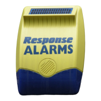
EXTERNAL SOLAR SIREN
The Siren is encapsulated within a tough polycarbonate
housing that also provides full protection against
adverse weather conditions.
An LED indicator unit is built into the Siren to act as
a visible deterrent and indication that the system is
active. The LEDs will slowly and alternately ash
whether the system is Armed or Disarmed. When an
alarm occurs the LEDs will ash rapidly together.
An integral tamper switch provides additional security
protection to the Siren and will immediately trigger an
alarm should any unauthorised attempt be made to
interfere with and remove the Siren cover.
The Siren is powered by a rechargeable sealed lead
acid battery. A solar panel mounted on the top of the
housing charges the battery during daylight hours.
During darkness, only a small amount of energy is
required to operate the Siren unit. A 9V Alkaline
PP3 battery is supplied to boost the initial power to
the unit when the system is rst activated until the
solar panel charges the main battery. (This battery is
only designed to last for a short period until the main
rechargeable battery has obtained sufcient charge).
The Siren unit incorporates the installation’s Jamming
Detection system which will (if activated) generate an
alarm if any attempt is made to continuously jam the
radio channel used for the system.
POSITIONING THE SOLAR SIREN
The Siren should be located as high as possible in a
prominent position on an external wall so that it can be
easily seen and heard. The Siren should be mounted
on a sound at surface so that the rear tamper switch is
not activated when mounted.
Ensure that the tamper switch does not fall into the
recess between brick courses as this could prevent
the switch from closing and give a permanent
tamper signal.
In order to provide the maximum amount of daylight to
the solar panel, the Siren should ideally be mounted on
a south facing wall. However, an easterly or westerly
position will sufce.
Mounting the device on a north facing wall should be
avoided as this could mean that during the short dark
days of winter months the solar panel may not receive