16
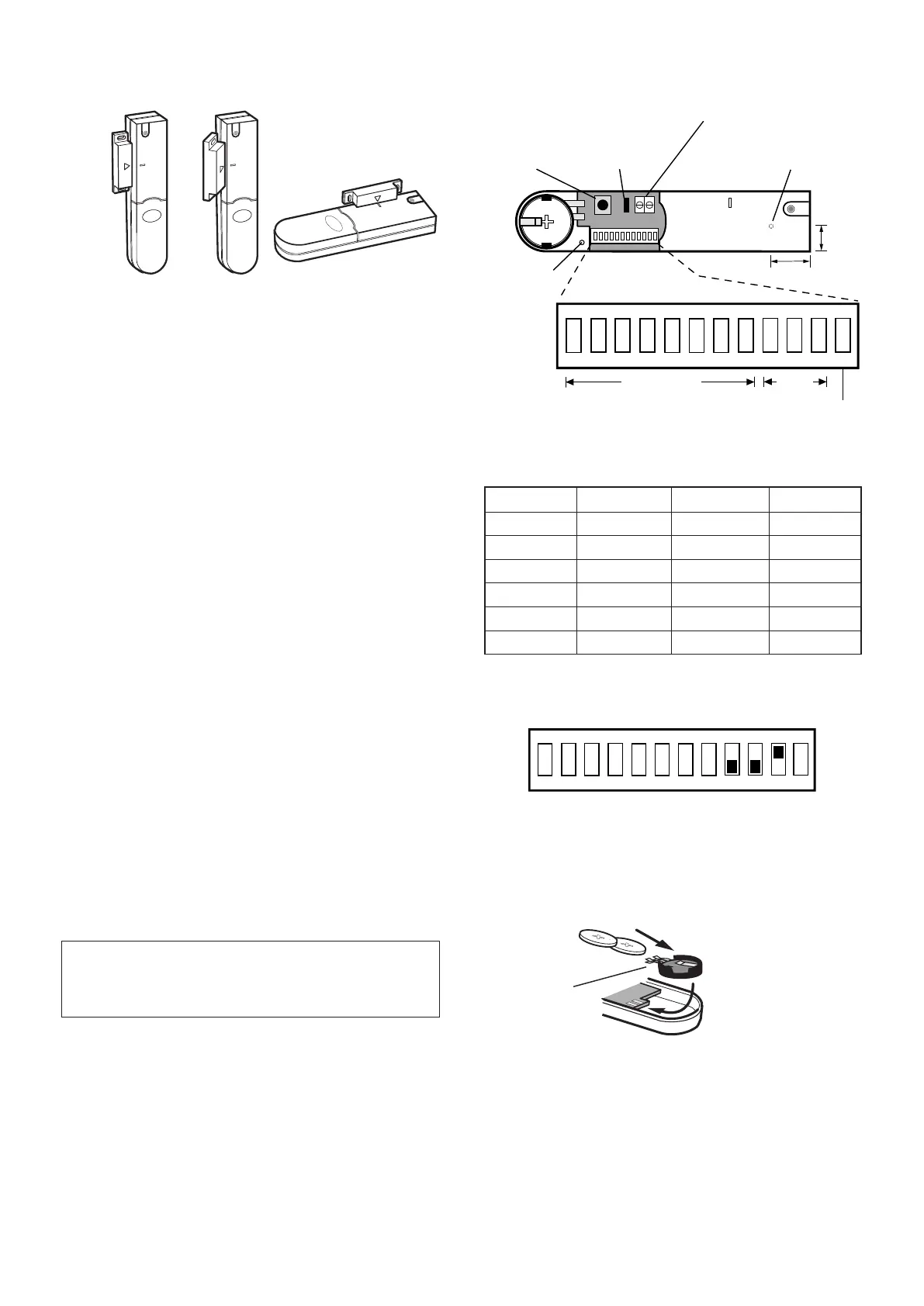
3. If xing the detector with screws rst remove the
battery holder by carefully tilting up the end and pulling
away from the printed circuit board (PCB).
The top of the Detector is secured by hanging the
keyhole slot over the head of the 10mm pan head
screw. The bottom of the Detector is secured using the
12mm counter-sunk head screw tted within the battery
compartment. Carefully drill out the centre of the xing
screw hole in the battery compartment using a 3mm
drill. Fit the Magnet using the two 15mm xing screws.
Do not over tighten the screws as this may distort or
damage the casing.
4. If an additional wired Magnetic Contact is required,
this should be wired to the terminal block provided in
the battery compartment. The wired contact should be
connected using a maximum length of 1.5 metres of
any of the following:
- 6 core alarm cable
- 2 core bell wire (6 x 0.2mm minimum)
- 2 core 24AWG wire
A cable entry cut-out is provided beside the terminal
block in the battery cover.
If an additional wired Magnetic Contact is connected to
the detector then Jumper Link S2 on the Circuit Board
must be removed.
5. Congure the House Code for the Magnetic Contact
Detector by setting DIP switches 1-8 to the same ON/
OFF combination as the House Code DIP switches in
all other system devices.
IMPORTANT: If an additional wired contact is not
connected, then the Jumper Link S2 must be tted
for the Detector to operate correctly.
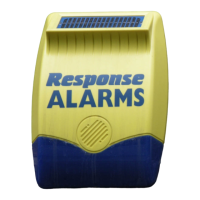
6. Congure the alarm zone which the detector will
operate on with DIP switches 9-11 as follows:
e.g. To congure the detector to operate on Zone 2 set
DIP switches 9,10 and 11 as follows:
Note: DIP switch 12 is not used.
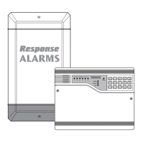
7. Slide the two batteries supplied into the battery
holder, ensuring that the + side is uppermost on each
battery as it is installed.
8. If necessary, ret the battery holder into the detector
ensuring that the spring clip connectors slide onto
either side of the circuit board.
9. Ret the battery cover.
DIP 9 DIP 10 DIP 11
Zone 1 OFF OFF OFF
Zone 2 OFF OFF ON
Zone 3 OFF ON OFF
Zone 4 OFF ON ON
Zone 5 ON OFF OFF
Zone 6 ON OFF ON
ON
1
2 3 4 5 6 7 8 9 10 11 12