Page 61 of 80
© Retrotec 2022
1. Turn the gauge on.
2. Check the battery power before beginning a test to ensure the gauge has enough power to
complete the test. (Plug the gauge in, or recharge batteries if needed).
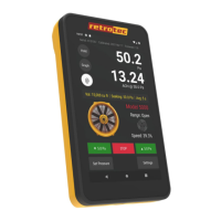
3. Select the appropriate device by tapping the device picture.
4. Select the Range Configuration installed in the fan by tapping on its picture.
5. Tap [Channel B] to select the required results to display. Note that the result displayed can be
changed at any point during the test.
6. Select an appropriate time averaging value for the test conditions.
7. Tap [Settings][Baseline Pressure and capture a baseline pressure reading.
8. Either press [Set Speed] to set the fan speed to a particular percentage, OR press [Set
Pressure] to control the fan to a particular building pressure.
9. To view estimated flow at the exact target pressure, use the [@] function.
10. Tap [Hold] to hold the results on the display to make them easier to copy down.
The gauge calculates Flow based on Pressure readings from the fan
The air flow being produced by the calibrated fan is a value that can be calculated based on the pressure
developed by the air moving across the inlet side of the fan towards the exhaust. Because the fan is
calibrated, there are known values describing the mathematical relationship between the fan pressure,
which is measured across the fan inlet, and the resulting air flow through the fan.
The Fan Pressure needed to calculate the fan flow is the difference between the pressure at the pickup and
the pressure in the vicinity of the inlet side of the fan. The fan pressure pickup is located inside the fan
near the inlet side of the fan. Self-referencing fans have the reference port built in, and it is placed to
measure the ambient pressure in the vicinity of the inlet side of the fan. Fan Pressure, FP, is determined
by setting the gauge to display pressure on [Channel B] and reading the resulting pressure on the gauge
when the room is at the test pressure.
Each fan and range combination has a different flow equation. For each fan and range combination
available, the variables needed to calculate flow are listed in Table 8.
The form of the flow equation depends on where the pickup for the Fan Pressure connected to the yellow
“ref B” port on the gauge is located with respect to the green “input B” port of the gauge.
Case 1: Flow Away from Operator
If the flow of the fan is away from the operator holding the gauge, then the gauge and the operator are on
the inlet side of the fan. Readings on [Channel A] in this case will always be negative, measuring the
induced pressure in the room.
Since both the fan pressure pickup and the reference for the fan pressure (yellow port on the fan and green
port on the gauge) are on the inlet side of the fan, [Channel B] will show the correctly referenced fan
pressure and can be used directly as the fan pressure, FP, value in the following flow equation:
=
(
|
|
× 1
)
×
(
+ × 3
)
× 4
Where:
FP is the fan pressure from Channel B displayed on gauge
RP is the room pressure from Channel A displayed on gauge
Case 2: Flow Toward Operator

 Loading...