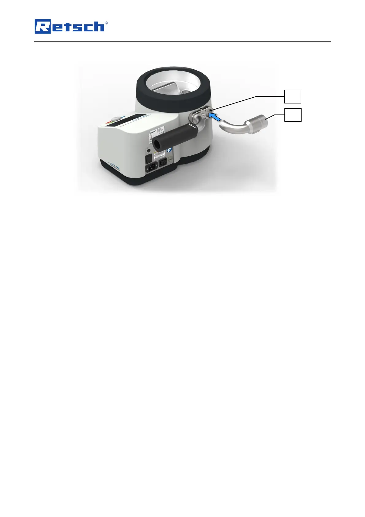
Insert the manual vacuum regulation (G) into the air outlet duct (E).
5.2.2 Adjustment of the Manual Vacuum Regulation
The manual vacuum regulation (G) has a lateral opening (G2) through which air is sucked in.
The size of the opening can be varied by means of a slider (G1). This allows to adjust the
desired negative pressure in the nozzle chamber (A).
When the opening is closed (1), the airflow from the nozzle (B) and thus also the negative
pressure in the nozzle chamber is at maximum. With the opening at maximum (4), the airflow
from the nozzle and thus the negative pressure in the nozzle chamber is at a minimum.
In between, the negative pressure can be infinitely adjusted by means of the slider (G1).
 Loading...