Company Registered in England No: 4167649 VAT Registration No: 732 5692 25 BS EN ISO 9001:2008 No: LRQ 0964389
+44 (0)1204 699959
enquiries@hyquip.co.uk
Hyquip Limited New Brunswick Street Horwich Bolton Lancashire BL6 7JB UK
www.hyquip.co.uk/web/index
About this product 19/60
RE 92100-01-B/09.2012, A4VSG Series 10, 11 and 30, Bosch Rexroth AG
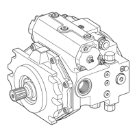
5.2.2 Functional description
Torque and rotational speed are applied to the drive shaft (1) by an engine. The drive
shaft is connected by splines to the cylinder(8) to set this in motion. With every
revolution, the pistons (9) in the cylinder bores execute one stroke whose magnitude
depends on the setting of the swashplate(11). The pistons hold the slipper pads
(10) onto the glide surface of the swashplate with the retaining plate(2) and guide
them along. The swashplate setting during a rotation causes each piston to move
over the bottom and top dead centers and back to its initial position. Here, hydraulic
fluid is fed in and drained out through the two control slots in the control plate(4)
according to the stroke displacement. On the high-pressure side(5) the hydraulic
fluid is pushed out of the cylinder chamber and into the hydraulic system by the
pistons. At the same time, hydraulic fluid flows into the growing piston chamber on
the low-pressure side(7). In a closed circuit, supported by the return and boost
pressure.
The swivel angle of the swashplate(11) is steplessly variable. Controlling the swivel
angle of the swashplate changes the piston stroke and therefore the displacement.
Adjusting the swashplate through the neutral position will change the direction of
flow (making reversing operation possible). The swivel angle is controlled
hydraulically by the stroke piston(3). The swashplate is mounted in swivel bearings
for easy motion and the neutral position is spring-centered. Increasing the swivel
angle increases the displacement; reducing the angle results in a corresponding
reduction in displacement.
Various control devices are available depending on requirements. Information
about this can be found in the corresponding data sheets for the controls, see
Table 1 "Required and supplementary documentation" on page5.
The following warning concerns all axial piston units with the control part HD and EP:
CAUTION
The spring return feature in the control device is not a safety device
The control device can stick in an undefined position due to internal contamination
(contaminated hydraulic fluid, abrasion or residual contamination from system
components). As a result, the volume flow of the axial piston unit will no longer
respond correctly to the operator's commands.
▶ Check whether the application on your machine requires additional safety
measures, in order to bring the driven consumer into a safe position (immediate
stop). If necessary, make sure that these are properly implemented.
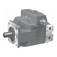
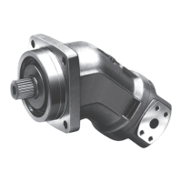
Pump
Control