Company Registered in England No: 4167649 VAT Registration No: 732 5692 25 BS EN ISO 9001:2008 No: LRQ 0964389
+44 (0)1204 699959
enquiries@hyquip.co.uk
Hyquip Limited New Brunswick Street Horwich Bolton Lancashire BL6 7JB UK
www.hyquip.co.uk/web/index
Installation 29/60
RE 92100-01-B/09.2012, A4VSG Series 10, 11 and 30, Bosch Rexroth AG
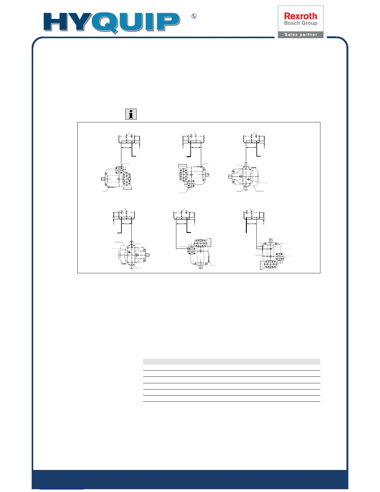
7.3.1 Below-reservoir installation (standard)
Below-reservoir installation means that the axial piston unit is installed outside of
the reservoir below the minimum fluid level.
Recommended installation positions: 1 and 2.
15 15 0
15 15 0
T
R(L)
K
3
K
3
R(L)
B(A)
B(A)
K
3
R(L)
R(L)
T
T
U
R(L)
T
R(L)
K
2
zu S
1)
a
min
SB
h
t min
h
min
zu S
1)
a
min
SB
h
t min
h
min
SB
zu S
1)
a
min
h
t min
h
min
K
2
SB SB SB
a
min
a
min
a
min
h
t min
h
min
h
t min
h
min
h
t min
h
min
zu S
1)
zu S
1)
zu S
1)
K
2
K
2
K
2
12
45 6
3
T, R(L),
K
2
, K
3
Fluid filling + air bleeding
(case drain port)
h
min
Minimum required spacing to
reservoirbottom(100mm)
A, B Pressure port a
min
When designing the reservoir, ensure
adequate distance between the
suction line and the case drain line.
This prevents the heated, return flow
from being drawn directly back into
the suction line.
S Suction port
U Bearing flushing
SB Baffle (baffle plate)
h
t min
Minimum required immersion depth
(200 mm)
Table 8: Below-reservoir installation
Installation position Filling / air bleeding housing
1 (drive shaft, horizontal) R(L)
2 (drive shaft, horizontal) T; R(L) plug
3 (drive shaft, horizontal) K
2
; R(L) plug
4 (drive shaft, horizontal) K
3
; R(L) plug
5 (drive shaft, vertically downward) R(L)
6 (drive shaft vertically upward) T; R(L) plug
1)
If an attachment pump is fitted, please note the information given in the related data sheet. For an overview of attachment pumps,
please refer to data sheetRE 92100.
Fig. 8: Below-reservoir installation: A4VSG with installation position 1–6