Rexroth EcoDrive 03 DKC**.3-040...200 Instructions for Use 5-11
DOK-ECODR3-DKC40*200UL-IB01-EN-P
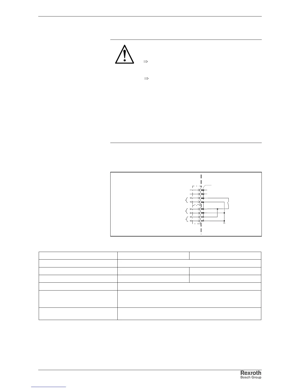
Holding brake (BR+, BR-)
DANGER
Dangerous movements! Danger to personnel
from falling or dropping axes!
⇒
The standard equipment motor brake or an external
brake controlled directly by the servo drive are not
sufficient to guarantee the safety of personnel!
⇒
Personnel safety must be acquired with higher-
ranking procedures:
Dangerous areas should be blocked off with fences
or grids.
Secure vertical axes against falling or slipping after
switching off the motor power by, for example:
- Mechanically securing the vertical axes
- Adding an external brake / clamping mechanism
- Balancing and thus compensating for the vertical
axes mass and the gravitational force
These connections control the holding brakes in the connected motors.
For the switching performance, see function description.
To connect external loads note allowed contact loads.
AP5298F1.FH7
0VB
X6
1
2
3
BR+
4
BR-
5
6
7
8
UB
0VB
holding brake
voltage connection for brake
U
B
device-external device-internal
voltage connection for brake
to additional DKCs
Fig. 5-26: Holding brake and voltage connection
Loadability of connections BR+, BR-:
Units DKC**.3-040-7, DKC**.3-100-7 DKC**.3-200-7
max. switching voltage: DC 40 V
max. switching current: DC 2 A DC 4 A
max. continuous current: DC 2 A DC 4 A
Minimum contact load: 100 mA
Guaranteed number of switches at
max. time constant of load <50ms
(L
Bremse
/(24V/I
Bremse
)):
250.000
Short-circuit and overload protection in
the row to the contact
present
Connection
BR+, BR-: