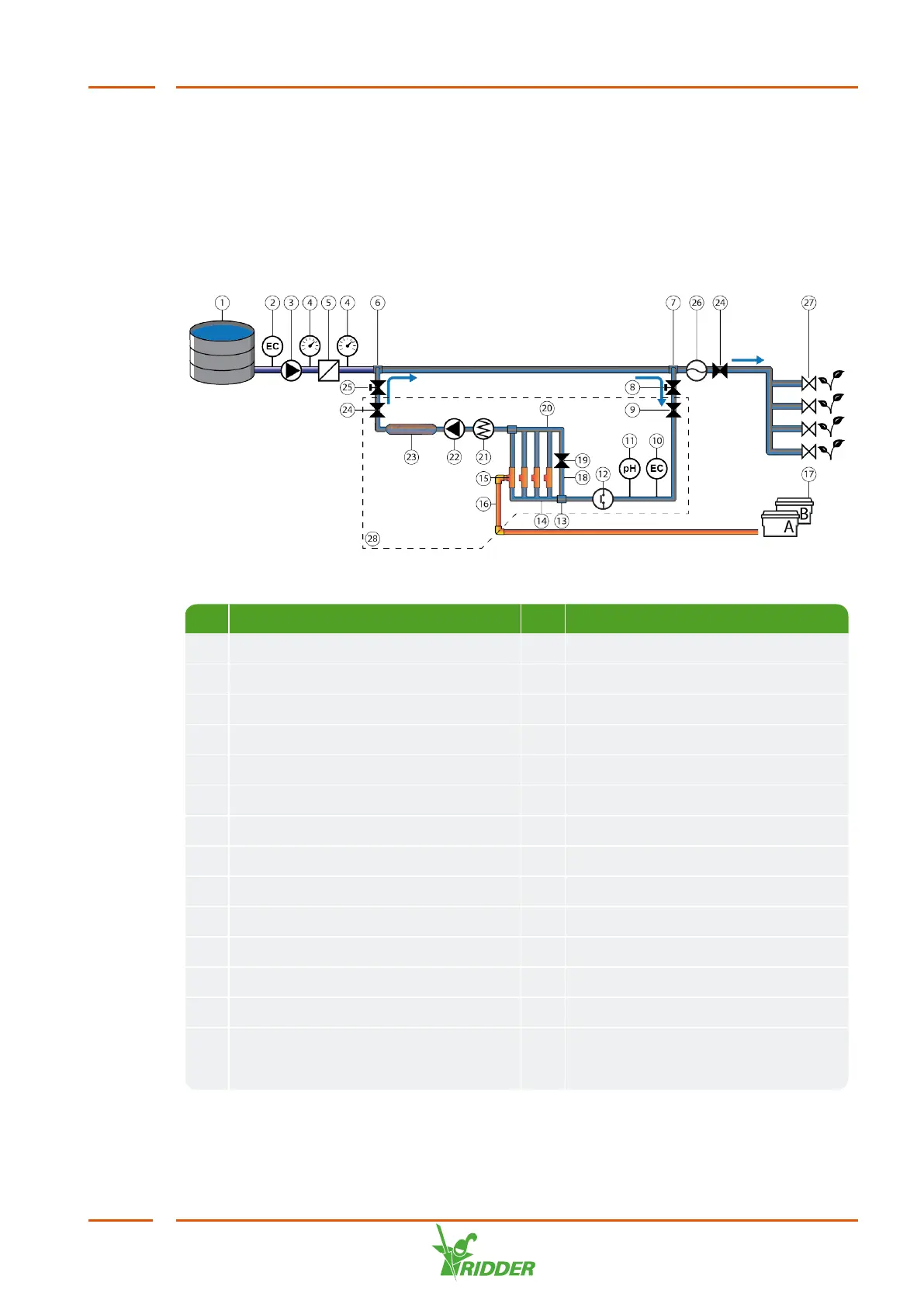
2.1 Principles of operation
No. Name No. Name
1 Fresh water tank 15 Venturi
2 EC sensor supply (optional) 16 Dosing channel
3 Main irrigation pump 17 Fertilizer tanks / acid tank
4 Pressure gauge 18 Compensation channel
5 Filter 19 PRV in compensation channel
6 HortiJet Pro outlet into main pipe 20 Collection pipe
7 HortiJet Pro inlet out of main pipe 21 Air release valve
8 Manual valve inlet 22 HortiJet pump
9 PRV (pressure reducing valve) 23 Mixing chamber
10 EC sensor (optional) 24 PSV (pressure sustaining valve)
11 pH sensor (optional) 25 Manual valve outlet
12 Pressure switch 26 Flow sensor (optional)
13 Dosing module inlet 27 Irrigation valve
14 Distribution pipe 28 The area within the box marks the
HortiJet Pro; the ‘bypass
fertigation system’.