Technical description of the burner
4.7 Firing rates
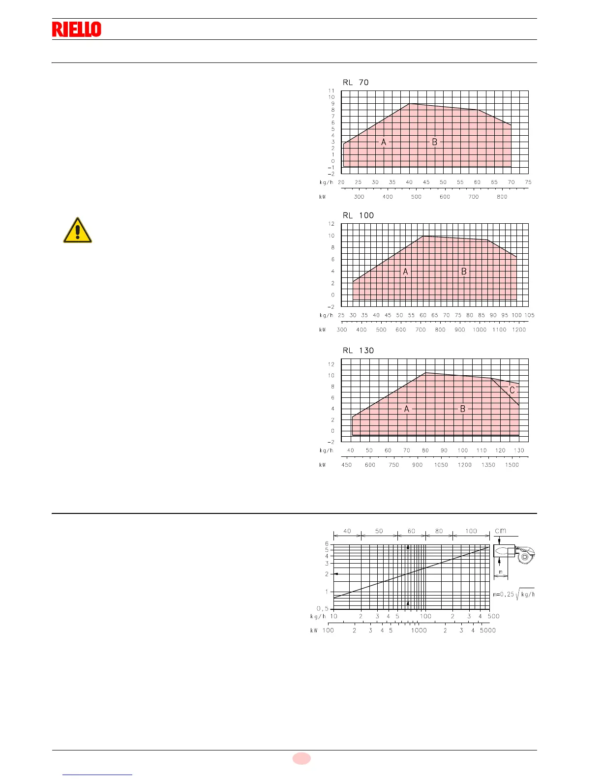
The RL 70 - 100 - 130 Model burners can work in two ways: one-
stage and two-stage.
1st stage DELIVERY must be selected within area A of the ad-
jacent diagrams.
2nd stage DELIVERY must be selected within area B (and C for
model RL 130). This area provides the maximum delivery of the
burner in relation to the pressure in the combustion chamber.
The work point may be found by plotting a vertical line from the
desired delivery and a horizontal line from the pressure in the
combustion chamber. The intersection of these two lines is the
work point which must lie within area B.
In order to utilize also area C (RL 130) it is necessary to perform
the calibration of the combustion head as explained on pag. 17.
4.8 Test boiler
The firing rates were set in relation to special test boilers in ac-
cordance with the methods defined in EN 267 standards.
Fig. 4 indicates the diameter and length of the test combustion
chamber.
Example:
delivery 65 kg/hour:
diameter = 60 cm; length = 2 m.
Whenever the burner is operated in a much smaller commercial-
ly-available combustion chamber, a preliminary test should be
performed.
The firing rate value (Fig. 3) has been obtained
considering an ambient temperature of 20 °C, an
atmospheric pressure of 1013 mbar (approx. 0 m
above sea level), and with the combustion head
adjusted as shown on pag. 16.