In case of remote-reset, connect a push-button with a nor-
mally open contact (NA) between the terminal 3 and the neu-
tral of the control box (for example, terminals 15, 16, 17 and
18).
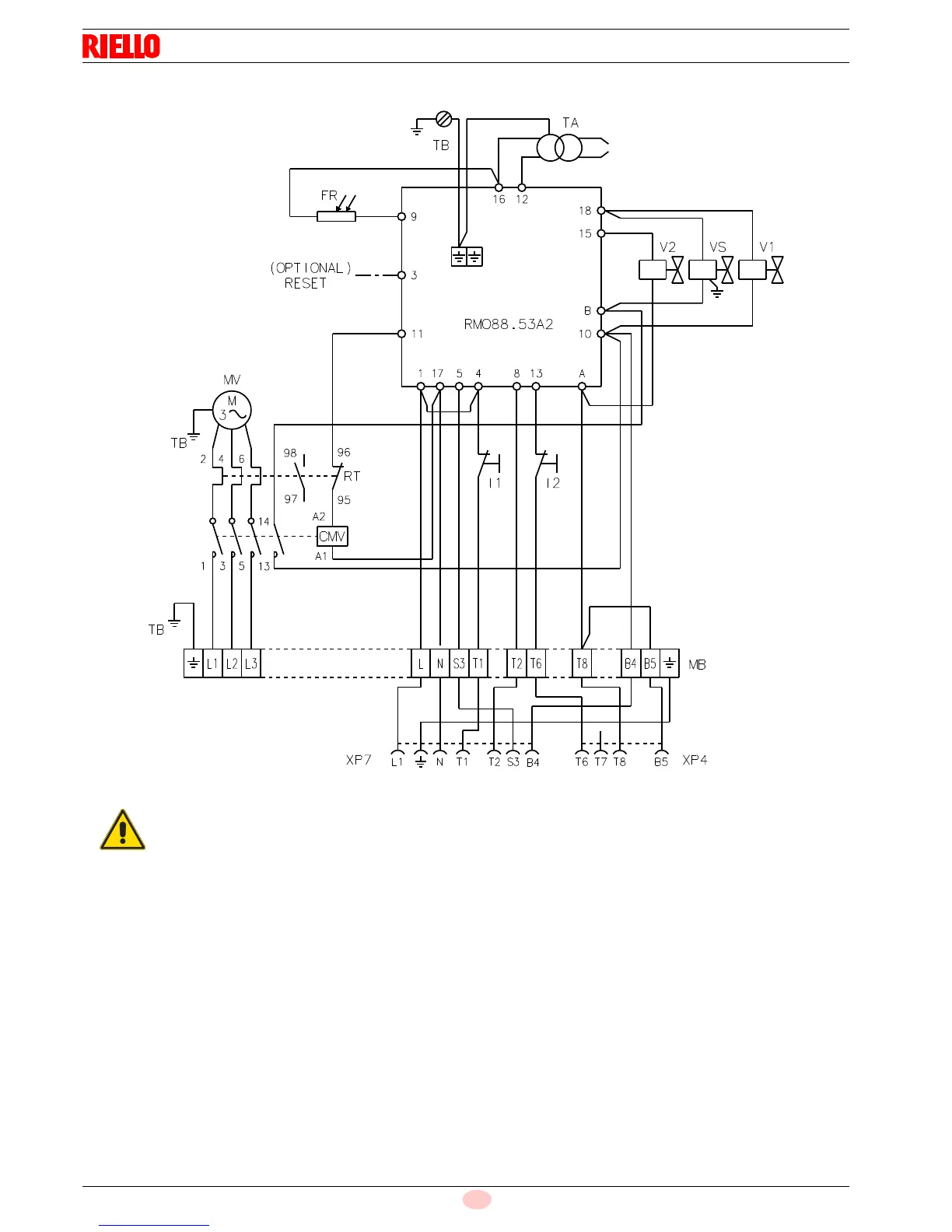
Key to layout (Fig. 23)
CMV Motor contactor
FR Photocell
I1 Switch: burner off - on
I2 Switch: 1st - 2nd stage operation
MB Terminal strip
MV Fan motor
RMO88.53A2 Control box
RT Thermal cut-out
TA Ignition transformer
TB Burner ground (earth) connection
V1 1st stage solenoid valve
V2 2nd stage solenoid valve
VS Safety solenoid valve
XP4 4 pole socket
XP7 7 pole socket
The burners leave the factory preset for 400V
power supply.
If 230V power supply is used, change the motor
connection from star to delta and change the set-
ting of the thermal cut-out as well.