Electrical system
6.1.3 Electrical wiring to be completed by the
installer
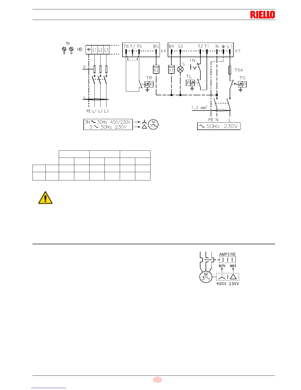
Fuses and cables cross-section (Fig. 24), see Tab. L.
Cross-section when not indicated: 1.5 mm
2
.
Tab. L
Key to layout (Fig. 24)
h1 1st stage hourcounter
h2 2nd stage hourcounter
IN Manual burner stop switch
MB Terminal strip
S Remote lock-out signal
TB Burner ground (earth) connection
TL Limit control device system:
This shuts down the burner when the boiler temperature
or pressure exceeds the setpoint value.
TR High-low mode control device system:
This controls operating stages 1 and 2 and is necessary
only for two-stage operation.
TS Safety control device system:
This operates when TL is faulty.
X4 4 pole plug
X7 7 pole plug
6.2 Calibration of thermal relay
This is required to avoid motor burn-out in the event of a signifi-
cant increase in power absorption caused by a missing phase.
• If the motor is star-powered, 400V, the cursor should be posi-
tioned to "MIN".
• If the motor is delta-powered, 230V, the cursor should be po-
sitioned to "MAX".
Even if the scale of the thermal cut-out does not include rated mo-
tor absorption at 400V, protection is still ensured in any case.
NOTE
The burners leaves the factory preset for 400V power sup-
ply. If 230V power supply is used, change the fan motor
connection from star to delta and change the setting of the
thermal cut-out as well.
The burners are factory set for two-stage operation and
must therefore be connected to control device TR.
Alternatively, if single stage operation is required, instead of
control device TR install a jumper lead between terminals
T8 and T6 (Fig. 24).
The burner is factory set for two-stage operation
and it must therefore be connected to the TR re-
move control device to command fuel valve V2.
Alternatively, if single stage operation is required,
instead of control device TR install a jumper lead
between terminal T8 and T6 (Fig. 24).