Start-up, calibration and operation of the burner
7.3 Burner operation
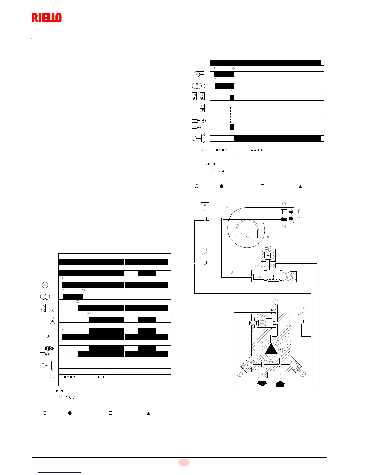
7.3.1 Burner starting
Starting phases with progressive time intervals shown in sec-
onds:
• Control device TL closes.
After about 3s:
• 0s: The control box starting cycle begins.
• 2s: The fan motor starts.
• 3s: The ignition transformer is connected.
The pump 3) sucks the fuel from the tank through the
piping 1) and the filter 2) and pumps it under pressure to
delivery. The piston 4) rises and the fuel returns to the
tank through the piping 5) - 7). The screw 6) closes the
by-pass heading towards suction and the solenoid
valves 8) - 11) - 16), de-energized, close the passage to
the nozzles.
The hydraulic cylinder 15), piston A, opens the air gate
valve: pre-purging begins with the 1st stage air delivery.
• 22s: Solenoid valves 8) and 16) open and the fuel passes
through the piping 9) and filter 10) and is then sprayed
out through the nozzle, igniting when it comes into con-
tact with the spark. This is the 1st stage flame.
• 29s: The ignition transformer switches off.
• 36s: If the control device TR is closed or has been replaced
by a jumper wire, the 2nd stage solenoid valve 11) is
opened and the fuel enters the valve 12) and raises the
piston which opens two passages: one to piping 13), fil-
ter 14), and the 2nd stage nozzle, and the other to the
cylinder 15), piston B, that opens the fan air gate valve
in the 2nd stage.
The starting cycle comes to an end.
For further details see pag. 29.
For further details see pag. 29.
*
Off Yellow Green Red