Start-up, calibration and operation of the burner
Example RL 70 - 1st stage nozzle 6.0 GPH:
2,3 (Fig. 27) notch aligned with index 1) (Fig. 27).
When the adjustment is terminated lock the hex element 2)
(Fig. 28) with the ring nut 1).
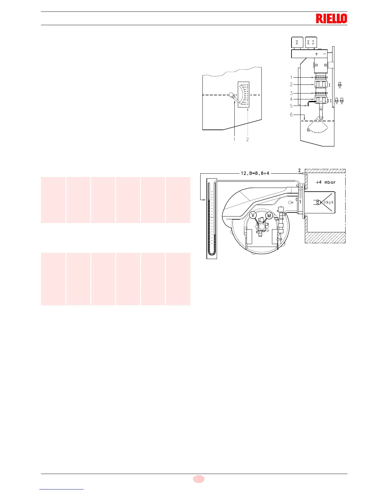
• 2nd stage fan air gate valve
Set switch 2) (Fig. 26 on page 26) to the 2nd stage position and
adjust the air gate valve 6) (B, Fig. 27) by turning the hex element
4) (B, Fig. 27), after having loosened the ring nut 3)(B, Fig. 27).
Air pressure at attachment 1) (Fig. 28) must be approximately the
same as the pressure specified in (Tab. N) plus the combustion
chamber pressure measured at attachment 2).
Refer to the example in the adjacent figure.
in order to facilitate adjustment of hex elements 2) and 4) (A,
Fig. 27), use a 3 mm Allen key 5) (B, Fig. 27).
Gas oil
Kerosene
(1) With shutter 4) (Fig. 12 on page 17) retracted
mbar = air pressure in 1) with zeropressure in 2)
Tab. N
RL 70 RL 100 RL 130
kg/h mbar kg/h mbar kg/h mbar
40
50
60
70
8.5
8.6
8.8
9.2
60
70
80
90
100
7.2
7.7
8.4
9.3
11.0
80
90
100
110
120
130
130
7.0
7.2
7.6
8.1
9.0
11.0
8.5
(1)
RL 70 RL 100 RL 130
kg/h mbar GPH mbar kg/h mbar
40
45
50
55
60
70
7.2
7.4
7.7
8.0
8.2
8.3
58
65
73
80
86
99
6.8
7.1
7.5
8.2
9.8
11.3
80
90
95
100
115
120
130
130
7.5
7.9
8.1
8.5
9.8
10
12.4
8.5