Technical description of the burner
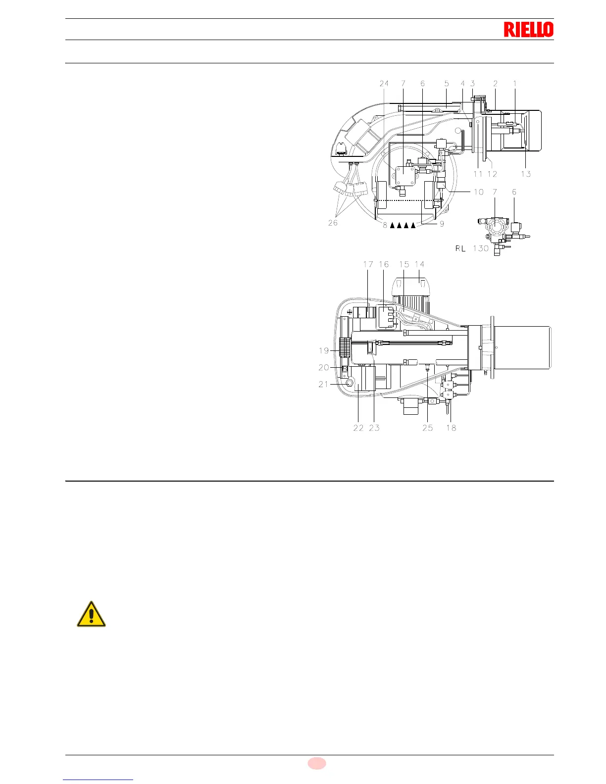
4.9 Burner description
1 Ignition electrodes
2 Combustion head
3 Screw for combustion head adjustment
4 Screw for fixing fan to flange
5 Slide bars for opening the burner and inspecting the com-
bustion head
6 Safety solenoid valve
7 Pump
8 Air inlet to fan
9 Air gate valve
10 Hydraulic cylinder for regulation of the air gate valve in 1st
and 2nd stage positions. When the burner is not operating
the air gate valve is fully closed in order to reduce heat dis-
persion from the boiler due to the flue draught which draws
air from the fan suction inlet.
11 Fan pressure test point
12 Boiler mounting flange
13 Flame stability disk
14 Electrical motor
15 Extensions for slide bars 5)
16 Ignition transformer
17 Motor contactor and thermal cut-out with reset button
18 1st and 2nd stage valve assembly
19 Terminal strip
20 Two switches:
- one "burner off - on"
- one for "1st - 2nd stage operation"
21 Fairleads for wiring carried out by the installer
22 Control box with lock-out pilot light and lock-out reset but-
ton
23 Flame inspection window
24 Pump pressure adjustment
25 Photocell for flame presence control
26 Sockets for electrical connections
Two types of burner failure may occur:
Control box lock-out: if the control box 22)(Fig. 5) pushbutton
(red led) lights up, it indicates that the burner is in lock-out.
To reset, hold the pushbutton down for between 1 and 3 seconds.
Motor trip: release by pressing the pushbutton on thermal cutout
17)(Fig. 5).
4.10 Standard equipment
2 - Flexible hoses
2 - Gaskets for flexible hoses
2 - Nipples for flexible hoses
1 - Thermal insulation screen
2 - Extensions 15)(Fig. 5) for slide bars 5)(Fig. 5)
(for models with 385 mm blast tube)
4 - Screws to secure the burner flange to the boiler: M 12 x 35
2 - Plugs for electrical connections
1 - Instruction booklet
1 - Spare parts list