Installation
5.11.3 Single-pipe circuit
In order to obtain single-pipe working it is necessary to unscrew
the return hose, remove the by-pass screw 5)(Fig. 20 - Fig. 21 on
page 22) and then screw the plug 2)(Fig. 20 - Fig. 21 on
page 22).
The distance “P” must not exceed 10 meters in order to avoid
subjecting the pump's seal to excessive strain; the distance "V"
must not exceed 4 meters.
For the priming pump loosen the screw 3)(Fig. 20) in order to
bleed off the air contained in the suction line and wait until the fuel
flows out.
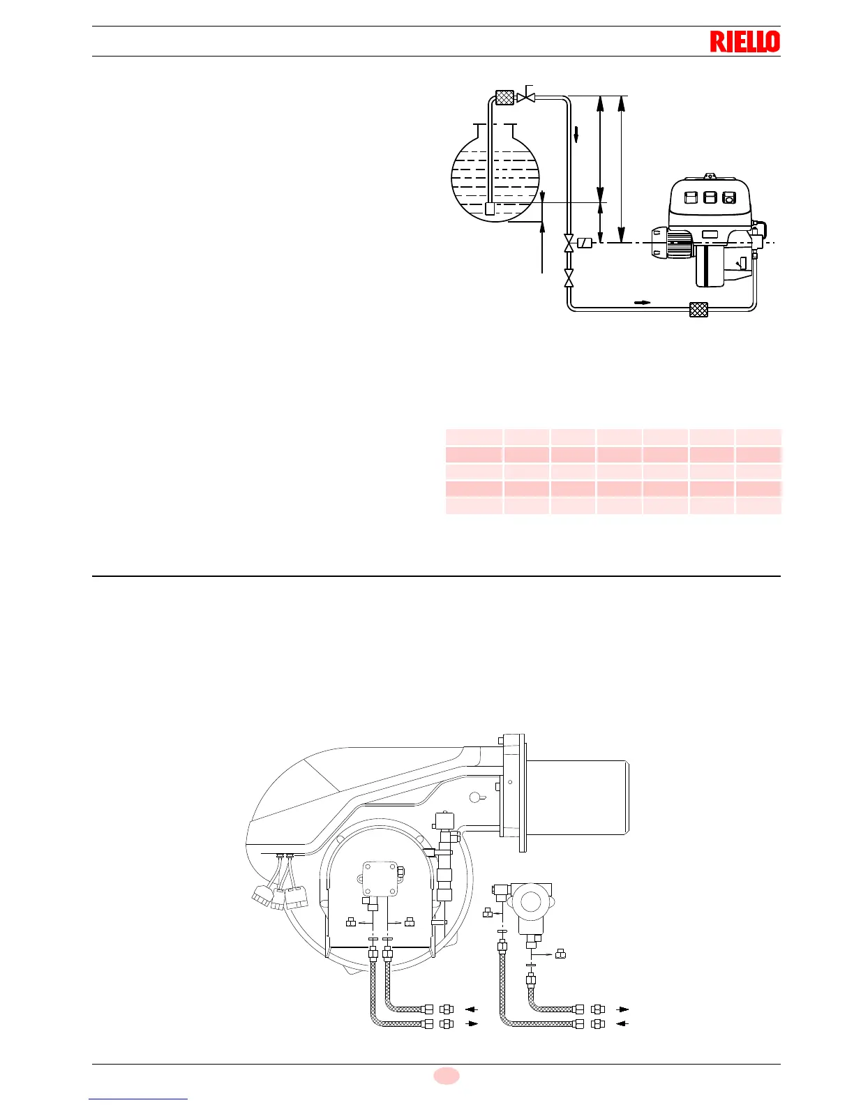
Key (Fig. 18)
H Pump/Foot valve height difference
L Piping length
ø Inside pipe diameter
1 Burner
2 Pump
3 Filter
4 Manual on/off valve
5 Suction line
6 Foot valve
7 Rapid closing manual valve remote controlled (only Italy)
8 On/off solenoid valve (only Italy)
11 Tank filter
Tab. I
5.12 Hydraulic connections
The pumps are equipped with a by-pass that connects return line
and suction line. The pumps are installed on the burner with the
by-pass closed by screw 6)(Fig. 20 - Fig. 21 on page 22).
It is therefore necessary to connect both hoses to the pump.
The pump will break immediately if it is run with the return line
closed and the by-pass screw inserted.
Remove the plugs from the suction and return connections
of the pump.
Insert the hose connections with the supplied seals into the
connections and screw them down.
Take care that the hoses are not stretched or twisted during
installation.
Install the hoses where they cannot be stepped on or come
into contact with hot surfaces of the boiler and where they
do not hamper the opening of the burner.
Now connect the other end of the hoses to the suction and return
lines by using the supplied nipples.
+ H
- H
(m)
L (m)
RL 70-100
Ø (mm)
RL 130
Ø (mm)
10 12 14 12 14 16
+ 4,0 39 81 100 71 138 150
+ 3,0 34 71 100 62 122 150
+ 2,0 29 61 100 53 106 150
+ 1,0 25 51 100 44 90 150
+ 0,5 22 46 100 40 82 150