Installation
5.9.1 Combustion head calibration
At this point check, for model RL 130, whether the maximum de-
livery of the burner in 2nd stage operation is contained in area B
or in area C of the firing rate. See pag. 12.
If it is in area B then no operation is required.
If, on the other hand, it is in area C:
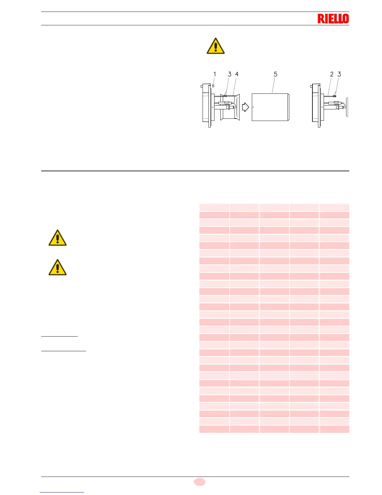
– Unscrew the screws 1)(Fig. 12) and disassemble the blast
tube 5).
– Unscrew the screws 3) and remove the shutter 4).
– Tighten the screws 3) on the rod 2).
– Now refit the blast tube 5) and the screws 1).
Once this operation has been carried out (if it was required), se-
cure flange 7)(Fig. 9) to the boiler plate interposing the supplied
gasket 8).
Use the 4 screws provided after having protected the thread with
antiscruffing products (high-temperature grease, compounds,
graphite).
5.10 Nozzle installation
5.10.1 Choice of nozzles for 1
st
and 2
nd
stage
The burner complies with the emission requirements of the
EN 267 standard.
In order to guarantee that emissions do not vary, recommended
and/or alternative nozzles specified by Riello in the Instruction
and warning booklet should be used.
Both nozzles must be chosen from among those listed in Tab. F.
The first nozzle
determines the delivery of the burner in the 1st
stage.
The second nozzle
works together with the 1st nozzle to deter-
mine the delivery of the burner in the 2nd stage.
The deliveries of the 1st and 2nd stages must be contained within
the value range indicated on pag. 10.
Use nozzles with a 60° spray angle at the recommended pres-
sure.
The two nozzles usually have equal deliveries, but the 1st stage
nozzle may have the following specifications if required:
• a delivery less than 50% of the total delivery whenever the
back-pressure peak must be reduced at the moment of fir-
ing: the burner allows good combustion values also with a
ratio 40 - 100 % between the 1st and 2nd stage;
• a delivery higher than 50% of the total delivery whenever
the combustion during the 1st stage must be improved.
GAS OIL
Tab. F
(1)
We get the indicated delivery when both nozzles are work-
ing and gas oil has the following characteristics: density
0.84 kg/dm3 - viscosity 4.2 cSt/20 °C - temperature 10 °C
The use of nozzles other than those specified by
Riello S.p.A. and inadequate regular maintenance
may result into emission limits non-conforming to
the values set forth by the regulations in force, and
in extremely serious cases, into potential hazards
to people and objects.
The manufacturing company shall not be liable for
any such damage arising from nonobservance of
the requirements contained in this manual.
GPH
kg/h (1)
kW
12 bar
10 bar 12 bar 14 bar
5.00 19.2 21.2 23.1 251.4
5.50 21.1 23.3 25.4 276.3
6.00 23.1 25.5 27.7 302.4
6.50 25.0 27.6 30.0 327.3
7.00 26.9 29.7 32.3 352.3
7.50 28.8 31.8 34.6 377.2
8.00 30.8 33.9 36.9 402.1
8.30 31.9 35.2 38.3 417.5
8.50 32.7 36.1 39.2 428.2
9.00 34.6 38.2 41.5 453.1
9.50 36.5 40.3 43.8 478.0
10.0 38.4 42.4 46.1 502.9
10.5 40.4 44.6 48.4 529.0
11.0 42.3 46.7 50.7 553.9
12.0 46.1 50.9 55.3 603.7
12.3 47.3 52.2 56.7 619.1
13.0 50.0 55.1 59.9 653.5
13.8 53.1 58.5 63.3 693.8
14.0 53.8 59.4 64.5 704.5
15.0 57.7 63.6 69.2 754.3
15.3 58.8 64.9 70.5 769.7
16.0 61.5 67.9 73.8 805.3
17.0 65.4 72.1 78.4 855.1
17.5 67.3 74.2 80.7 880.0
18.0 69.2 76.4 83.0 906.1
19.0 73.0 80.6 87.6 956.0
19.5 75.0 82.7 89.9 980.9
20.0 76.9 84.8 92.2 1005.8
21.5 82.7 91.2 99.1 1081.7
22.0 84.6 93.3 101.4 1106.6