Installation
The nozzle for the 1st stage of operation is the one lying beneath
the firing electrodes (Fig. 14 on page 18).
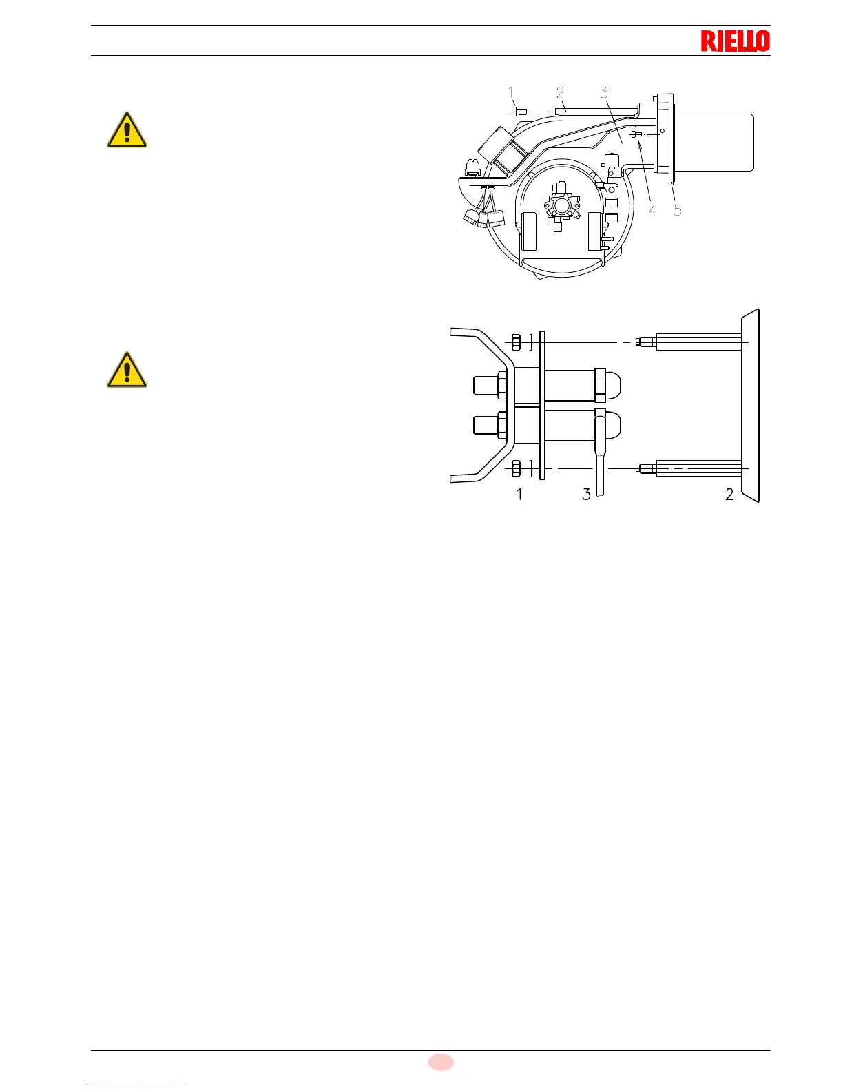
Finally remount the burner 3)(Fig. 15) to the slide bars 2) and
slide it up to the flange 5), keeping it slightly raised to prevent the
flame stability disk from pressing against the blast tube.
Tighten the screws 1) on the slide bars 2) and screws 4) fixing the
burner to the flange.
If it proves necessary to change a nozzle with the burner already
fitted to the boiler, proceed as outlined below:
– Retract the burner on its slide bars as shown in (Fig. 9 on
page 16).
– Remove the nuts 1)(Fig. 16) and the disk 2).
– Use spanner 3)(Fig. 16) to change the nozzles.
When fitting the burner on the two slide bars, it is
advisable to gently draw out the high tension ca-
bles until they are slightly stretched.



 To Next Page