Roche Diagnostics
Urisys 1100® · ≥5.7 · Operator's Manual · 9.0
12 3. System description
3. System description
3.1 Measuring principle
The test strip is placed on a sliding test strip tray, and a
stepping motor moves it under the reading head, which
remains stationary. The analyzer reads the reference pad,
followed by each of the test pads on the strip.
The reading head contains LEDs that emit light at various
wavelengths. Reading is done electro-optically, as
follows:
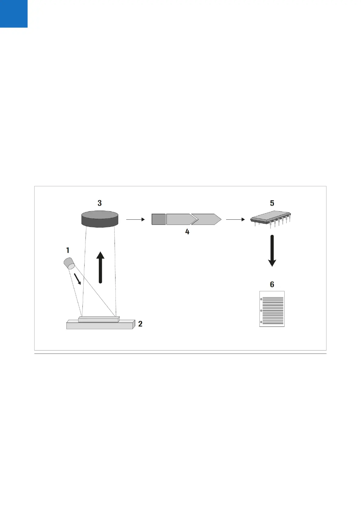
w Measuring principle
The LED (1) emits light of a defined wavelength on to the
surface of the test pad (2) at an optimum angle. The light
hitting the test zone is reflected more or less intensely
depending on the color produced on the test pad, and is
picked up by the detector, a phototransistor (3)
positioned directly above the test zone. The
phototransistor sends an analogue electrical signal to an
A/D converter (4), which changes it to digital form. The
microprocessor (5) then converts this digital reading to a
relative reflectance value by referring it to a calibration
standard.
 Loading...