210 Rockwell Automation Publication 1769-UM021I-EN-P - May 2018
Chapter 8 Use I/O Modules with CompactLogix 5370 L2 Controllers
Input Filter Selections
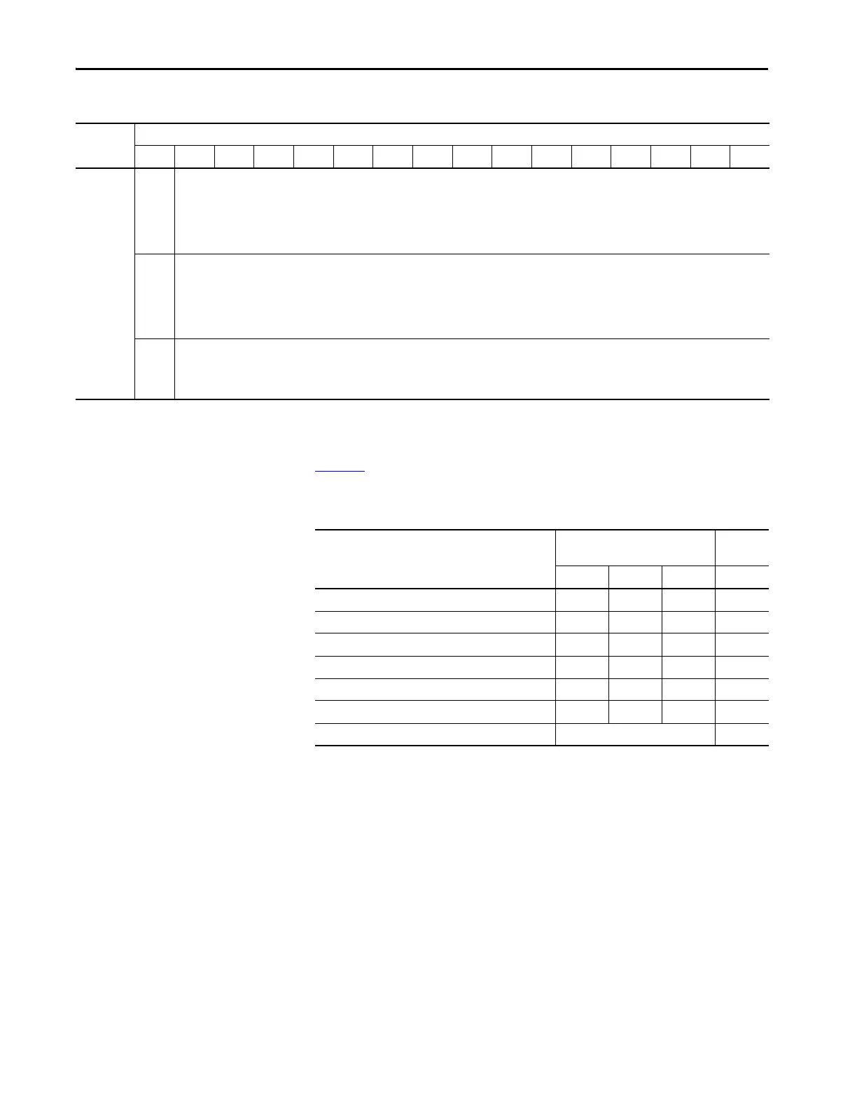
Tab le 20 lists the bit value combinations you can use to select a filter setting for
a channel.
You use bits 0…3 in words 2, 8, 14, and 20 to make this selection.
Where
(cont.)
Clamp
High
Data
Value
Channel
x
Use this bit to configure the Clamp High data value for a channel.
Clamp
Low
Data
Value
Channel
x
Use this bit to configure the Clamp Low data value for a channel.
Ramp
Rate
Channel
x
Use this bit to set the Ramp Rate value for a channel.
Table 19 - CompactLogix 5370 L2 Controller Embedded Analog I/O Module Configuration Image Array (continued)
Word Bit
1514131211109876543210
Table 20 - Input Filter Selections
Filter Value
Bit Settings
(Words 3, 9, 15, and 21)
Bit 03 Bit 02 Bit 01 Bit 00
60 Hz
0000
50 Hz 0001
10 Hz 0 0 1
250 Hz 0011
500 Hz 0100
1 kHz 0 1 0 1
Spare
(1)
(1) An attempt to write a non-valid (any Spare value) or Not Used bit configuration into the Input Filter Response Select field causes
a Module Configuration Error (contained in the Mod_Condition Array).
Values 6…15
 Loading...


