Rockwell Automation Publication 1769-UM021I-EN-P - May 2018 41
Install the CompactLogix 5370 L1 Controller Chapter 2
7. Plug the removable connector back into the controller.
8. Secure the removable connector in place.
9. Turn on power to the external 24V DC power source.
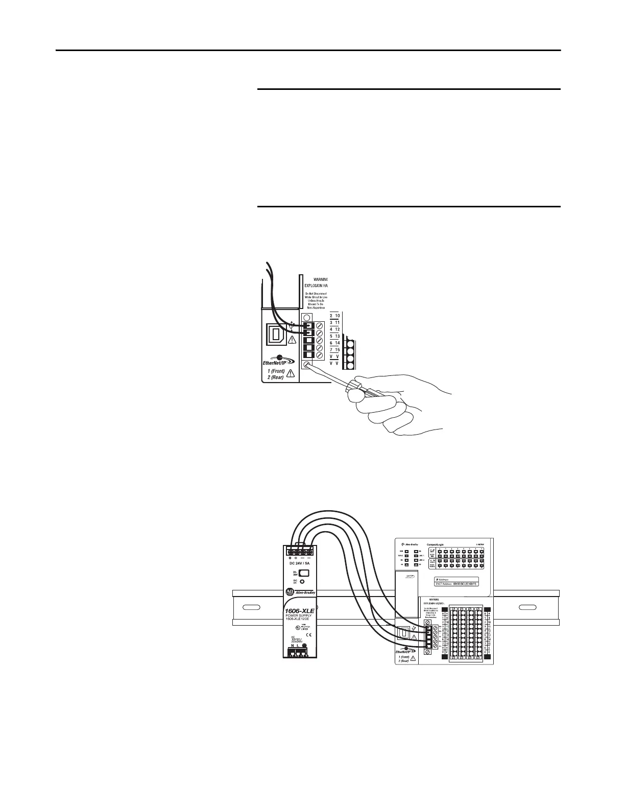
The following graphic shows an external 24V DC power source that is
connected to a CompactLogix 5370 L1 controller.
IMPORTANT If your application requires a power control device, for example, a
switch or relay, between the external 24V DC power source and the
CompactLogix 5370 L1 controller to control when the controller is
powered, you must install the power control device at the VDC+
terminal on the removable connector.
If you install the power control device at the VDC- terminal, the
CompactLogix 5370 L1 controller can have problems powering up or
powering down properly.
 Loading...


