Publication 1794-UM066B-EN-E - March 2015
36 Rack Optimized Discrete I/O
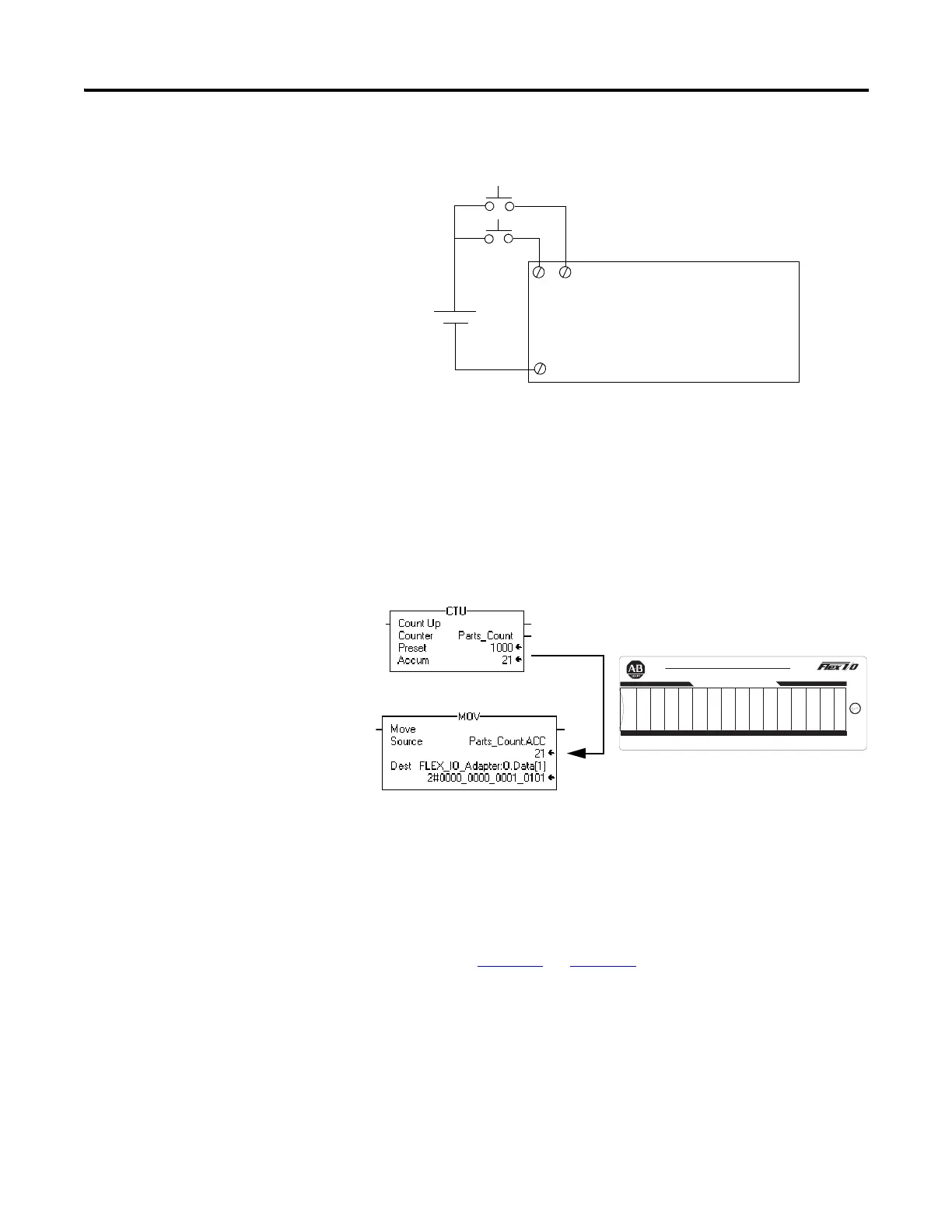
1. Remove power from the FLEX I/O and wire inputs 0 and 2 of the
1794-IB16 FLEX I/O input module as shown in the following figure:
2. Restore power to the FLEX I/O.
3. Restore the RSLogix 5000 software window and place the controller in
Run mode.
4. Repeatedly press and release the momentary switch at Input 0 (Count) on
the 1794-IB16 input module.
Each time you press the switch the Parts_Count accumulated value
increments on the screen and the LEDs of the 1794-OB16 output module
increment in binary.
5. Press and release the momentary switch at Input 2 (Reset) on the
1794-IB16 input module.
The accumulated value of the Parts_Count reset to zero and all of the
LEDs on the 1794-OB16 output module turn off.
This completes the Rack Optimized Discrete I/O example.
Chapter Summary
This chapter described how to set up and use rack optimized discrete I/O. The
next chapter describes how to add analog I/O modules to a configuration using
direct connection.
For more information on wiring and interpreting status LED
indicators on the I/O modules, refer to the I/O module publications
1794-IN093
and 1794-IN094.
Count
Reset
24V
+
-
1794-IB16
16 (COM)
02
151413121110987654321
0
24 VDC SOURCE OUTPUT
1794±OB16
2
Allen-Bradley
LEDs on Output Module will increment in binary.
Accumulated Value will
increment and move to
Output Module.
 Loading...