EasyManuals Logo

Rockwell Automation Allen-Bradley 1794-AENTR User Manual

Rockwell Automation Allen-Bradley 1794-AENTR
84 pages
To Next Page IconTo Next Page
To Previous Page IconTo Previous Page
Page #59 background imageLoading...
Page #59 background image
51 Publication 1794-UM066B-EN-E - March 2015
Appendix
A
Interpret Status Indicators
Overview
The faceplates of the 1794-AENT and 1794-AENTRXT adapters are provided
with status indicators that display the Module Status, Network Status, and Link
Status for both links.
Status Indicators
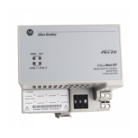
1794-AENTR, 1794-AENTRXT Module
Use the following table to determine the indicator conditions and status.
Status Indicator Identification
Indicator State Status
Link 1 or Link 2 (individually) Off No link exists. Verify network cabling. Correct
as necessary.
Solid green Link exists at 100 Mbps.
Flashing green I/O is being transmitted or received at 100
Mbps.
Flashing yellow I/O is being transmitted or received at 10
Mbps.
Solid yellow Link exists at 10 Mbps.
44560
Network status
Module status
Link 1 status
Link 2 status
1794-AENTR shown

Table of Contents

Questions and Answers:

Question and Answer IconNeed help?

Do you have a question about the Rockwell Automation Allen-Bradley 1794-AENTR and is the answer not in the manual?

Rockwell Automation Allen-Bradley 1794-AENTR Specifications

General IconGeneral
Communication ProtocolEthernet/IP
Network AddressConfigurable via software
Current Draw, Max200 mA
Shock30 g
Data Rate10/100 Mbps
Number of Ports1
Port TypeRJ45
MountingDIN Rail
Product TypeEtherNet/IP Adapter
Series1794
Power Supply Voltage24V DC
Operating Voltage19.2V to 30V DC
Operating Temperature-20°C to 60°C
Storage Temperature-40°C to 85°C
Relative Humidity5% to 95% (non-condensing)
CertificationsCE, UL, cUL

Related product manuals