14 Rockwell Automation Publication 20B-IN017B-EN-P - September 2011
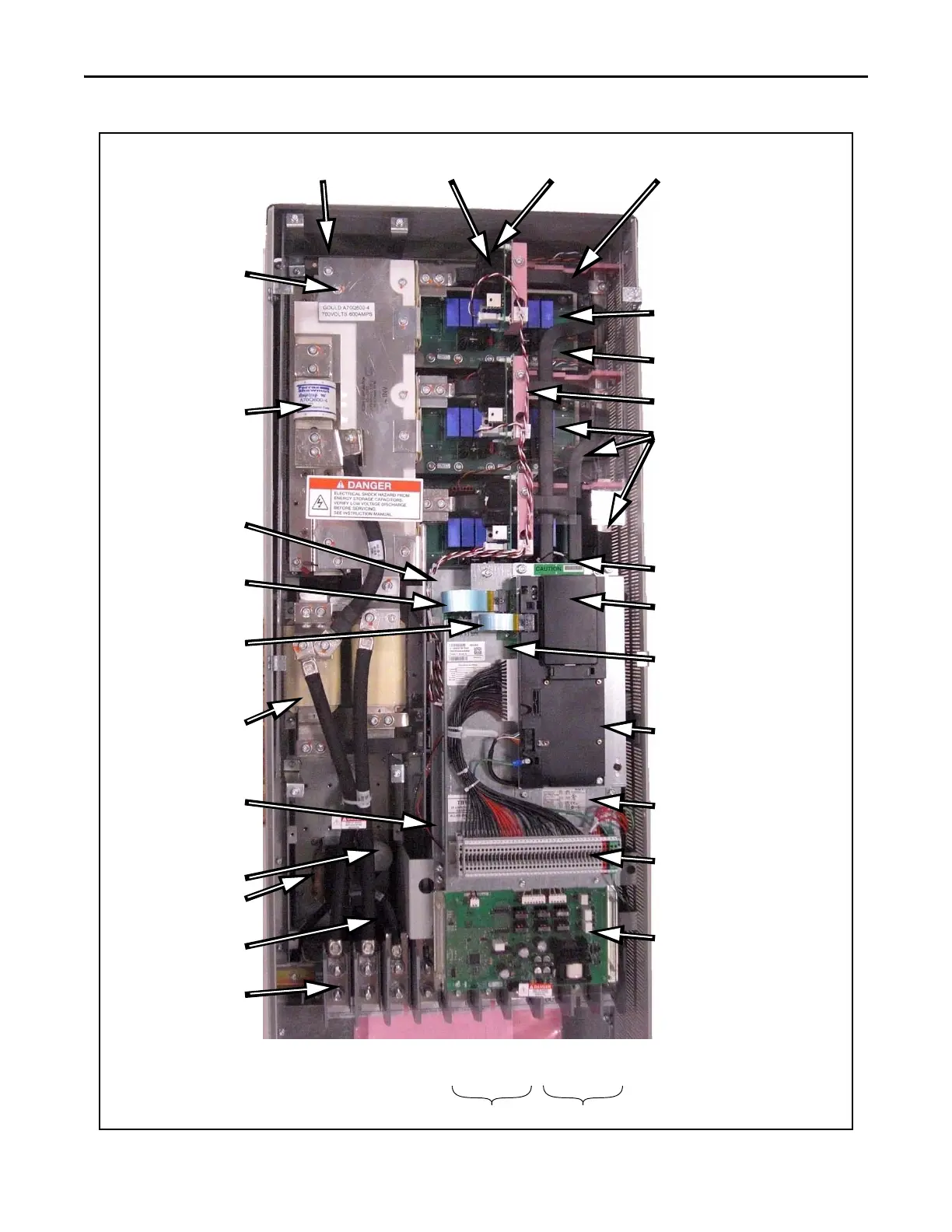
Chapter 1 Component Diagrams and Torque Specs
AC input drive is shown.
MOV Location
Inverter Snubber Board (U)
(V and W not visible in this image)
Current Transducer
(quantity: 3)
Gate Interface Board
Heatsink Thermal
Sensor location
Motor Bus Bars (U, V, W)
W
Inverter Power Module IGBT (U)
(V and W below U)
U
V
W Phase
U Phase
V Phase
T Phase
R Phase
S Phase
Precharge Board Assembly
Power Interface Board
location (under Main
Control Panel)
Transitional Bus Bar
Communications Panel
Main Control Panel
Bus Fuse
DC Link Choke
Main Control Panel Thermal Sensor
Wire
DC Capacitor Bank
(under Transitional Bus Bar)
HIM
(Blank shown on this Drive)
TB11
Switch Mode Power
Supply Board (under
Main Control Panel)
Ribbon Cable -
Main Control Board
to Comm Board
Main Control Board
(under HIM mounting)
Ribbon Cable - Main
Control Board to Power
Interface Board
IGBT Gate Harness and
CT Harness
Power Terminal Block
Tran sfo rme r
Capacitor for Fan
Motor ConnectionsAC Power Input Connections

 Loading...


