Rockwell Automation Publication 20B-IN017B-EN-P - September 2011 31
Component Replacement Procedures Chapter 3
Power Interface Board
Refer to the figures in Component Diagrams and Torque Specs on page 13 for
these instructions.
Remove Components
1. Read and follow the Safety Precautions on page 9 and Important Initial
Steps on page 11.
2. Perform Remove Main Control Panel Assembly on page 21
.
3. Remove remaining wiring
harnesses from the Power
Interface Board, including the
wiring between the Power
Interface Board and the
Switch Mode Power Supply
Board.
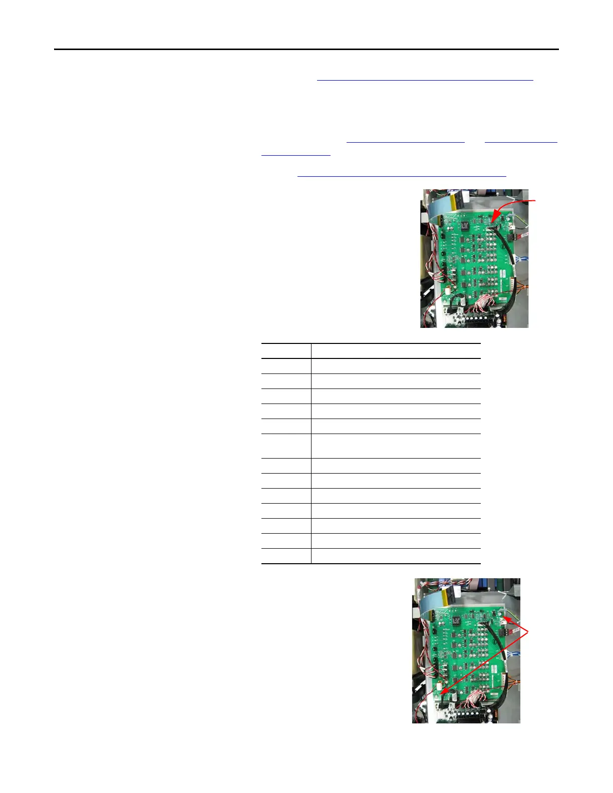
4. Remove the two Power Interface
Board mounting star screws
located at the upper right and
lower left corners of the board.
5. Using your fingers or needle-nose
pliers, squeeze the wings of each
of the nine (9) spacers and
remove the Power Interface Board
from the mounting plate.
Connector Connected Components
J1 Main Control Board
J10 Precharge Board (only on DC input systems)
J16 W Phase CT
J15 V Phase CT
J14 U Phase CT
J24 +Bus IN of Power Interface Board
to J1 of Precharge Board
J13 Switch Mode Power Supply Board
J12 Switch Mode Power Supply Board
J23 U, V, W positive gates (upper phase)
J18 U, V, W negative gates (lower phase)
TB2 TB11
J7 Monitor Wire to thermal sensors
TB1 TB11
J1
J10
J16
J15
J14
J24
J13 J12
J23
J18
TB2
TB1
J2
J7
Screws

 Loading...


