26 Rockwell Automation Publication 20B-IN017B-EN-P - September 2011
Chapter 3 Component Replacement Procedures
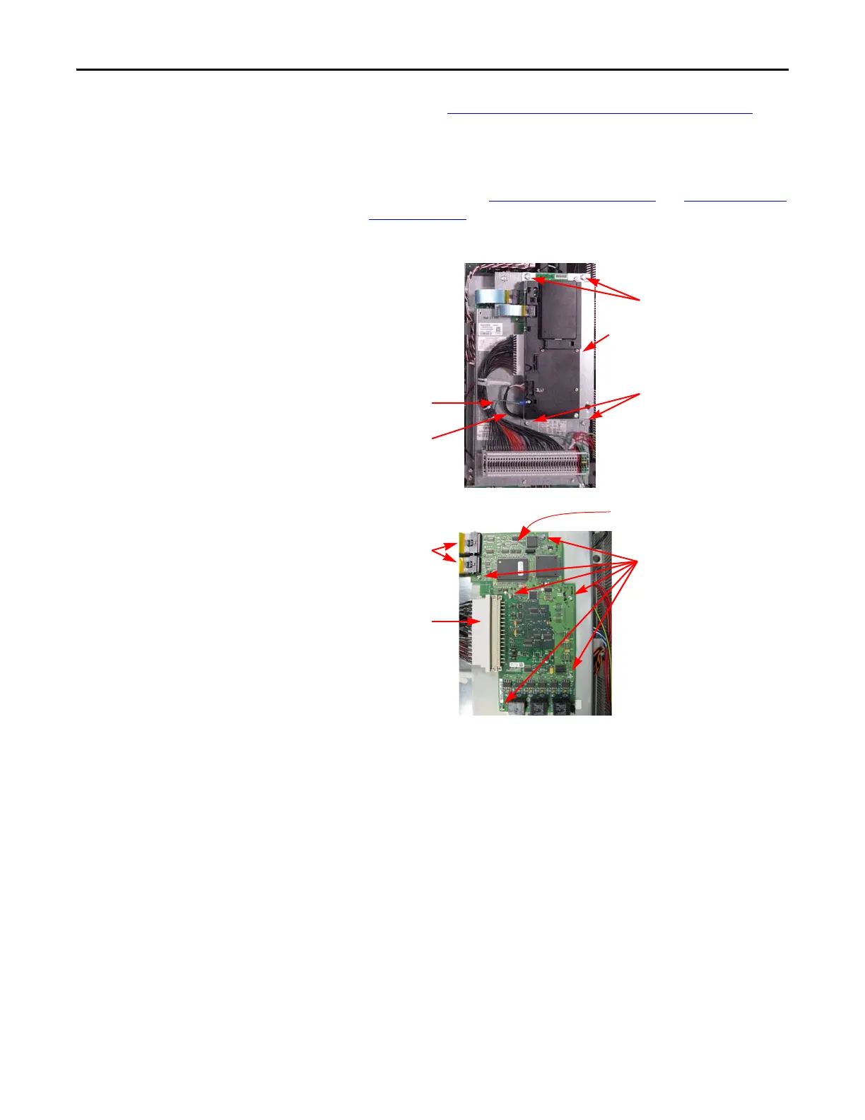
Main Control Board
Refer to the figures in Component Diagrams and Torque Specs on page 13 for
these instructions.
Remove Components
1. Read and follow the Safety Precautions on page 9 and Important Initial
Steps on page 11.
2. Remove safety shields as needed.
3. Unscrew the green/yellow ground wire from the Communications
Panel.
4. Remove the two nuts and two screws and washers for the
Communications Panel.
5. Disconnect both ribbon cables from the left side of the Main Control
Board.
6. Holding the Communications Panel, release the cable at the bottom of
the panel from its clamp and set the Communications Panel aside.
7. If needed, unscrew and disconnect the wire set going to TB11 from the
Main Control Board.
8. Unscrew the six (6) screws holding the Main Control Board.
9. Remove the Main Control Board.
Ribbon
Cables
Screws
To TB11
Ground Wire
Release Cable from
Clamp
Nuts
Screws and Washers
Communications Panel
Main Control Board
(Shown larger than in image above)
(Located over Main Control Panel)

 Loading...


