42 Rockwell Automation Publication 20B-IN017B-EN-P - September 2011
Chapter 3 Component Replacement Procedures
Inverter Power Module
(IGBT)
Important: Kit includes two (2) IGBT modules and two (2) Gate Interface
Boards. It is recommended that both IGBT modules for a phase be
replaced at the same time.
Refer to the figures in Component Diagrams and Torque Specs on page 13
for
these instructions.
Remove Components
1. Read and follow the Safety Precautions on page 9 and Important Initial
Steps on page 11.
2. Locate the Inverter Power Module to be replaced.
3. Perform Remove Transitional Bus Bar on page 23
.
4. Perform Remove Components on page 38
for the Inverter Snubber
Board over the IGBT modules to be replaced, but do not discard the
Inverter Snubber Board.
5. Remove the two Inverter Snubber brackets (two screws each) for each
board. Set aside.
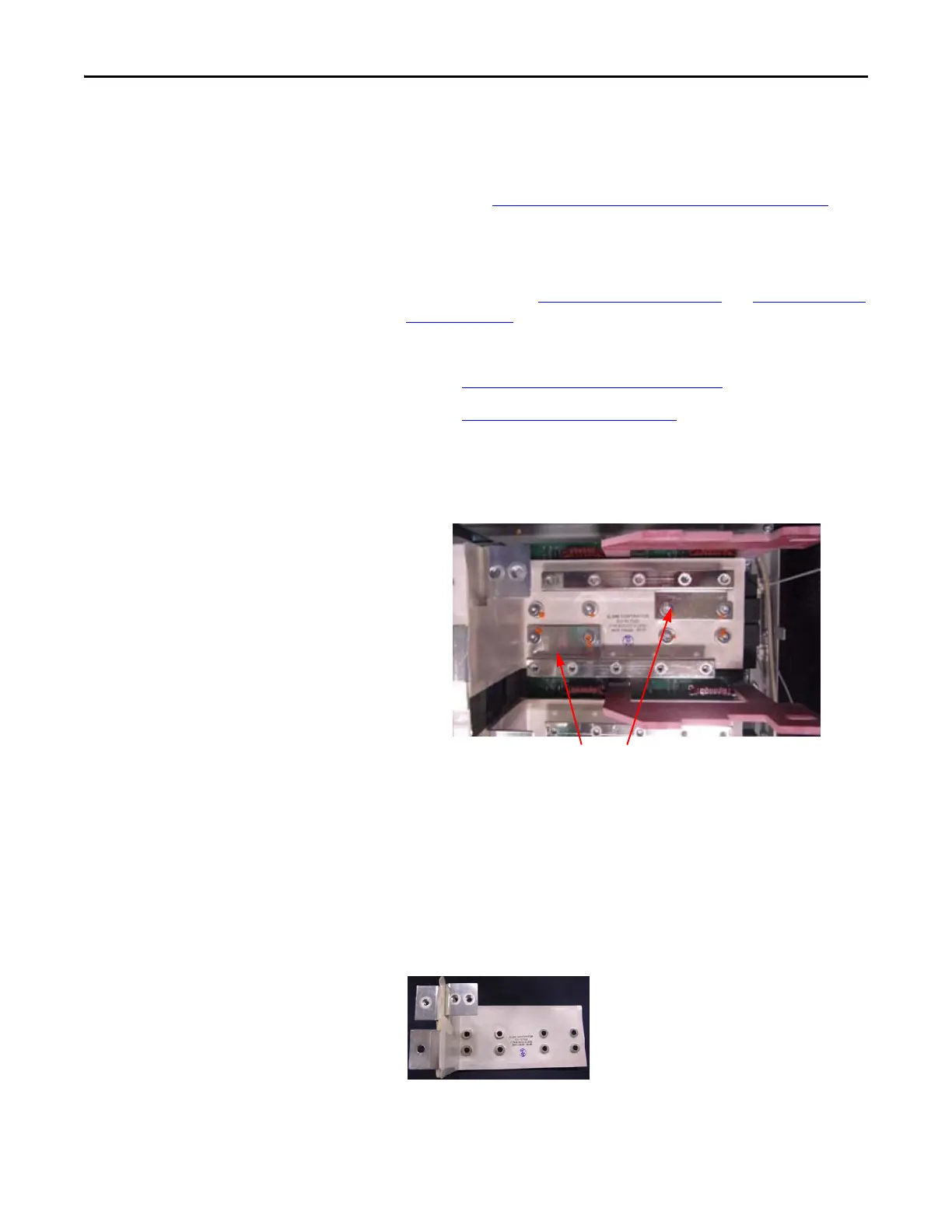
6. Disconnect the positive and negative IGBT bus bars (four T40 screws
each).
7. Using a pencil, mark the sides of the IGBT Bus Bar to note location for
later installation.
Exact positioning is critical for alignment of other components,
especially the Transitional Bus Bar unit.
8. Remove the IGBT Bus Bar from the modules. Set aside.
9. Disconnect connections for the Gate Interface Boards.
Inverter Snubber Brackets

 Loading...


