16 Rockwell Automation Publication 20B-IN017B-EN-P - September 2011
Chapter 1 Component Diagrams and Torque Specs
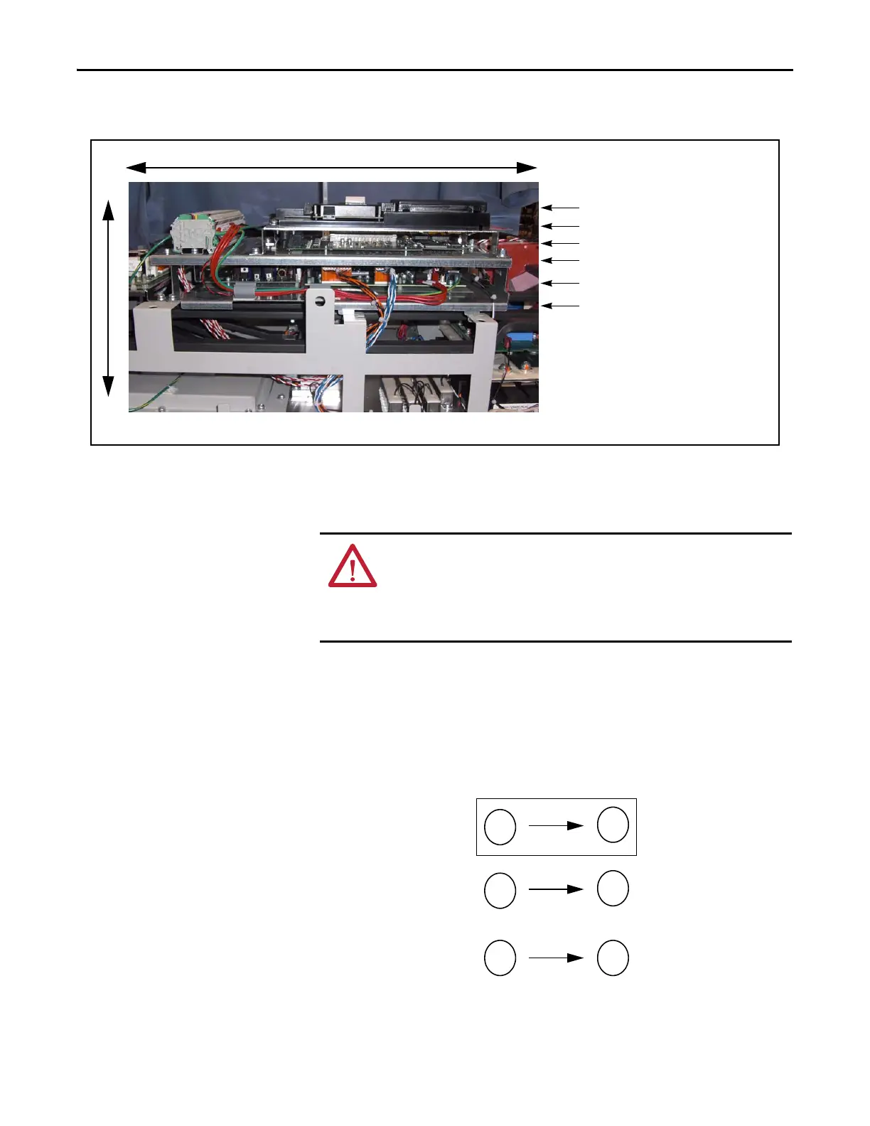
Main Control Panel Assembly
Fastener Torque
Specifications
Torque Sequence
The following illustrates initial and final tightening sequences for components
fastened to a heat sink using two, four, and six screws. Initial torque is 1/3 (33%)
of final torque, except six-point mountings, which require 0.7 N•m (6 lb•in) The
numeric illustration labels are for your assistance. Drive components do not carry
these labels.
Figure 1 - Two-Point Mounting
TB11 and Main Control Board
HIM
Stacking Panel
Switch Mode Power Supply Board and
Power Interface Board
Note: Components are shown as seen from right side without drive covers.
Components are listed left to right for
each level
Communications Panel
Main Control Panel
Bottom of Drive Top of Drive
Front
Back
ATTENTION: When mounting components to a drive’s heat sink,
component fastener torque sequences and tolerances are crucial to
component-to-heat sink heat dissipation.
Components can be damaged if initial tightening procedure is not
performed to specification.
1
2
Initial Sequence
1
2
12
Final Sequence

 Loading...


