Rockwell Automation Publication 20B-IN017B-EN-P - September 2011 21
Chapter 2
Basic Component Removal Procedures
The procedures in this section are required by many of the replacement
procedures described in this manual in addition to replacement of these
components themselves.
DO NOT perform any of the procedures in this section unless specified by the
instructions for the component you are replacing.
Remove Main Control Panel
Assembly
Refer to the figures in Component Diagrams and Torque Specs on page 13 for
these instructions.
Remove Components
1. Read and follow the Safety Precautions on page 9 and Important Initial
Steps on page 11.
2. Remove safety shields as needed.
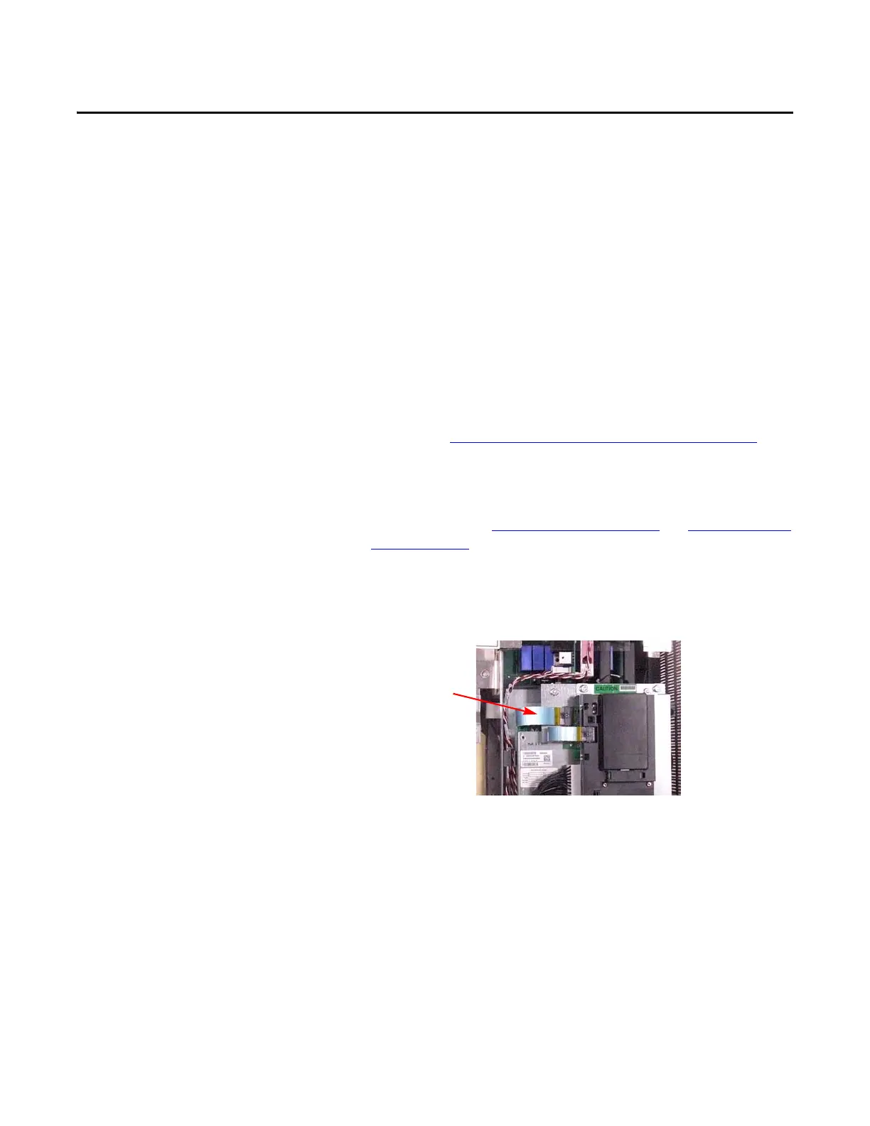
3. Remove the ribbon cable going from the Main Control Board (J2) to
the Power Interface Board (J1).
4. Remove the two screws on the Main Control Panel below TB11 for the
Main Control Board.
5. Verify that all wiring to lower side of TB11 is properly labeled and then
disconnect wiring from TB11.

 Loading...


