Rockwell Automation Publication 20B-IN017B-EN-P - September 2011 13
Chapter 1
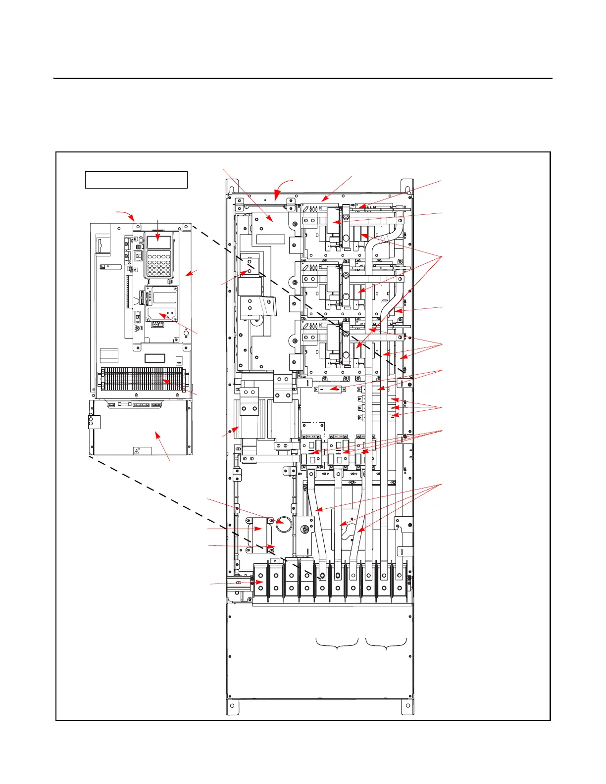
Component Diagrams and Torque Specs
Drive Components
AC input drive is shown.
+DC
USE 75° COPPER WIRE ONLY
TORQUE LARGE TERMINALS TO 10 N-m (87LB-IN)
-DC PE PE R-L1 T-L3 U-M1 V-M2 W-M3S-L2
RISK OF SHOCK
REPLACE AFTER
SERVICING
!
DANGER
TB11
25 AMPERES RMS
MAXIMUM
CAUTION
HOT SURFACES
ALLEN-BRADLEY
MADE IN U.S.A.
PE
!
Converter Snubber Boards (3)
with Converter Power SCR
Modules underneath
MOV Location
Inverter Snubber Boards (U,
V, W)
Inverter Snubber Resistors
Current Transducer
Gate Interface Board (U)
(V and W not shown)
Heatsink Thermal
Sensor location
Main Control Panel Assembly
Motor Bus Bars
AC Bus Bars (R, S, T)
W
Inverter Power Module IGBTs
(U, V, W) (under Inverter
Snubber Board)
U
V
W Phase
U Phase
V Phase
T Phase
R Phase
S Phase
Precharge Board
Assembly
TB2
J3 J1 J2
Power Interface Board
(under Main Control Panel)
TB11
Transitional Bus Bar
HIM
Communications
Module
Main Control Panel
(Stacking Panel (underneath)
Bus Fuse
Balancing Resistors
DC Link Choke
Main Control
Panel Thermal
Sensor
DC Capacitor Bank
(under Transitional Bus Bar)
Switch Mode Power Supply Board (under
Main Control Panel)
Power Terminal Block
Transformer
Capacitor
for Fan
Motor
Connections
AC Power Input
Connections

 Loading...


