32 Rockwell Automation Publication 20B-IN017B-EN-P - September 2011
Chapter 3 Component Replacement Procedures
Install Components
1. Install the new Power Interface Board.
Tighten board screws to 1.7 N•m (15 lb•in)
2. Reconnect all wiring except the ribbon cable going from the Power
Interface Board ( J1) to the Main Control Board ( J2).
3. Reinstall the Main Control Panel Assembly.
Tighten sheet metal screws to 3.2 N•m (28 lb•in)
4. Reconnect the ribbon cable going from the Power Interface Board (J1)
to the Main Control Board (J2).
5. Replace all safety shields and enclosure covers before applying power to
the drive.
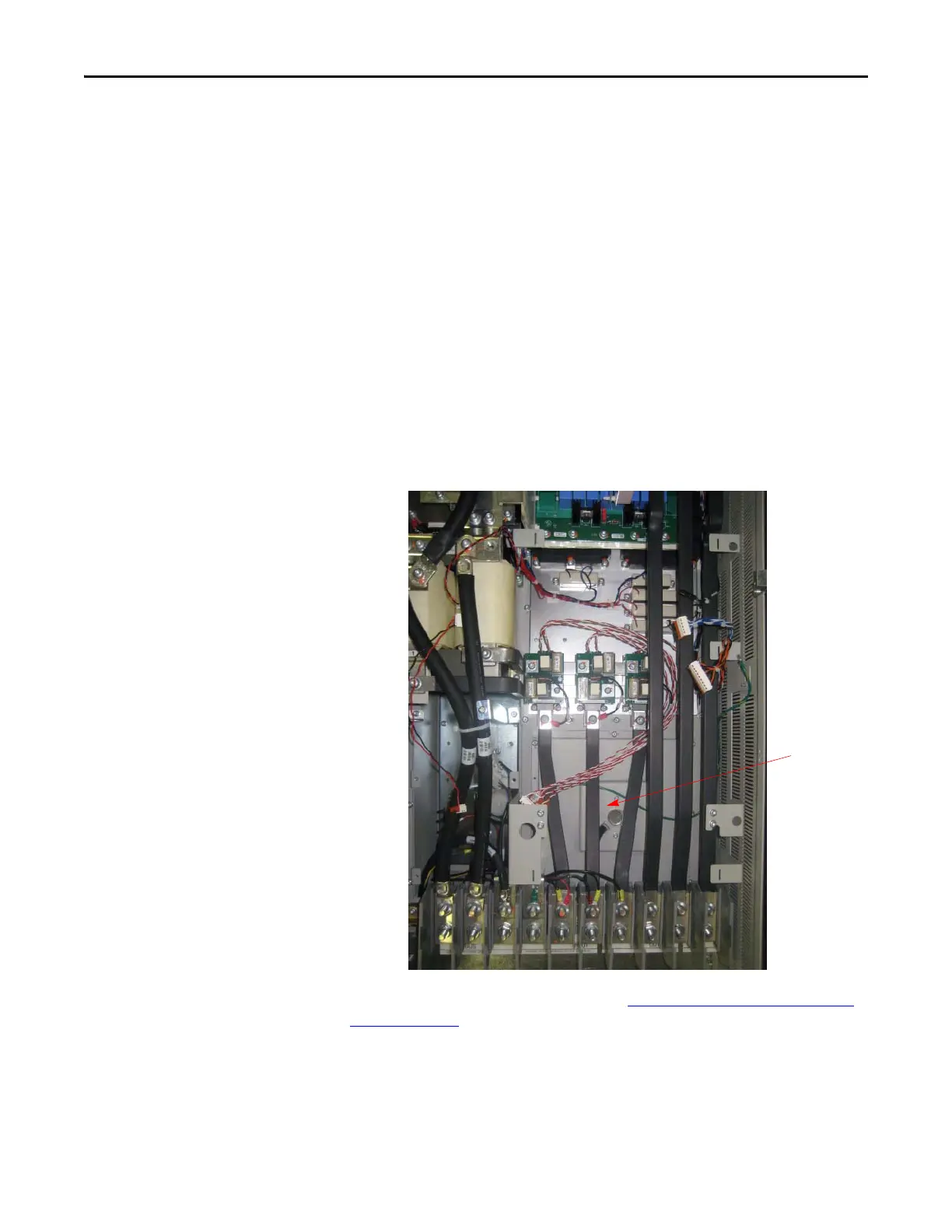
Fan
The Fan is located behind the Main Control Panel assembly and Precharge
Board.
Refer to the figure below and the figures in Component Diagrams and Torque
Specs on page 13 for these instructions.
Fan Assembly

 Loading...


