50 Rockwell Automation Publication 20B-IN017B-EN-P - September 2011
Chapter 3 Component Replacement Procedures
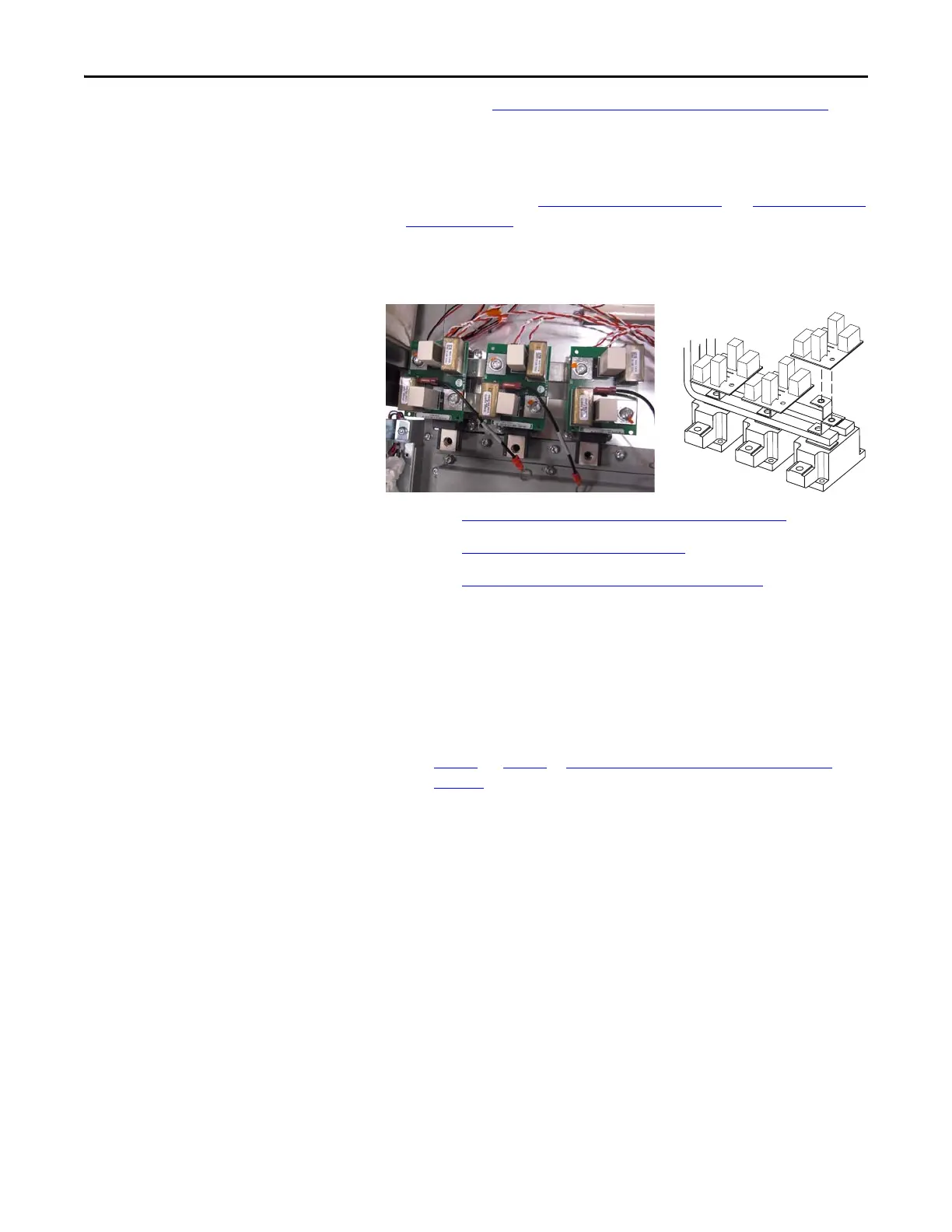
Converter Snubber Board - AC
Input Only
Refer to the figures in Component Diagrams and Torque Specs on page 13 for
these instructions.
Remove Components
1. Read and follow the Safety Precautions on page 9 and Important Initial
Steps on page 11.
2. Locate the Converter Snubber Board to be replaced. (Some wires below
shown disconnected.)
3. Perform Remove Main Control Panel Assembly on page 21
.
4. Perform Remove Stacking Panel on page 22
.
5. Perform Remove Precharge Board Assembly on page 23
.
6. For the T-Phase Converter Snubber Board, if the U-Phase Motor Bus
Bar must be removed for space considerations, then
• If space allows, remove the U-Phase Current Transducer and then
disconnect both ends of the U Phase Motor Bus Bar and remove it
to gain access to the Converter Snubber Board.
• Otherwise if space does not allow, using the instructions in
Step 2.
… Step 5. in Component Replacement Procedures on
page 25, remove all three Current Transducer assemblies and move
them to a safe location, but do not disassemble them.
7. Label and disconnect any push-on wire connector from the Converter
Snubber Board to be replaced.
8. Remove the two (2) T30 screws that secure the board. Remove the
board and discard.
Install Components
1. Install the new Snubber Board. Torque screws to 2.9 N•m (26 lb•in)
2. Reconnect all wires.
3. If removed, reinstall the U Phase Motor Bus Bar and torque screws to
9.0 N•m (80 lb•in)
4. Reassemble remaining components in reverse order.
5. Replace all safety shields and enclosure covers before applying power to
the drive.
R
S
T

 Loading...


